If some of you have Tram II's that can hardly deliver current for 45's you have faulty transformers and/ord heater supplies or something of that kind.
OK, i believe i have found the solution: Greg has been reading through the entire thread and mentioned to me today something about using different secondary windings for the heaters, but wasn't sure of the details.
Searching through the thread just now (i did read through it all myself last year, but the details are long forgotten), I found Bjarne's post (349) and Morten's followup (350), which teach us to use the 7.5V windings rather than the 5.5V windings.
Guess which windings my heater supply is using...
 Time to get out the soldering iron!
 ... and thanks yet again to the shared wisdom of Bjarne and Morten!
- richard
Well, there you go ") Always a good thing to make sure that all the ''basics'' are right before making conclusions that (in this case) the preamp is faulty and not designed right...
Always a good thing to make sure that all the ''basics'' are right before making conclusions that (in this case) the preamp is faulty and not designed right...
We have a saying here in Denmark that such problems are often ''fault 40'', meaning that the fault is about 40 cm away from where you think the problem is. Try to measure the distance from from your head when you sit staring into the preamp ''concluding'' that the preamp does not work
Always a good thing to make sure that all the ''basics'' are right before making conclusions that (in this case) the preamp is faulty and not designed right...We have a saying here in Denmark that such problems are often ''fault 40'', meaning that the fault is about 40 cm away from where you think the problem is. Try to measure the distance from from your head when you sit staring into the preamp ''concluding'' that the preamp does not work
BTW rab28... When you connect the heater supplies to the 7,5V windings you should check again, if your resistors in the RAW supplies are the right ones to get the correct voltage going into the Rod Coleman regulators... You will need something like 0,15 ohm, maybe a bit bigger since you guys down under seems to have quite high mains voltage.
Hi Morten,
i was not suggesting that the preamp was not designed correctly: as you know, the 5.5V/3A winding is the one used by the stock filament supply, and presumably is able to supply enough current in that implementation... the issues arises when the stock supply is replaced by a raw supply and the Coleman regulator circuit. We had assumed that the 5.5V/3A winding would be sufficient for this modified circuit, but this is clearly not the case.
It was clear to me that something was not right about our implementation, since you and Bjarne did not have this issue. As i see it, our mistake was that we did not read through this thread thoroughly!
Thanks Morten; will do -- although we are using a different raw supply circuit, so this may not apply....
As always, thanks for your continuing support.
- richard
...before making conclusions that (in this case) the preamp is faulty and not designed right...
i was not suggesting that the preamp was not designed correctly: as you know, the 5.5V/3A winding is the one used by the stock filament supply, and presumably is able to supply enough current in that implementation... the issues arises when the stock supply is replaced by a raw supply and the Coleman regulator circuit. We had assumed that the 5.5V/3A winding would be sufficient for this modified circuit, but this is clearly not the case.
It was clear to me that something was not right about our implementation, since you and Bjarne did not have this issue. As i see it, our mistake was that we did not read through this thread thoroughly!
... you should check again, if your resistors in the RAW supplies are the right ones to get the correct voltage
Thanks Morten; will do -- although we are using a different raw supply circuit, so this may not apply....
As always, thanks for your continuing support.
- richard
DIY DHT dampers
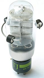
The above tube dampers are often recommend and used on the Tram2.
I dont like them. I found they could possibly induce noise in the Tram2 DHT's and were also quite poor at absorbing vibration compared to my simple and inexpensive DIY design.
I found it was possible to induce noise with these dampers and to make this really obvious I linked two of the metal ringed dampers together and lowered them near a DHT while the Tram2 was running. Appreciable noise came out the speaker and induced noise volume correlated with distance from the metal ring of the dampers to the DHT. When actually placed on the tube the metal would be even nearer. Noise can be expected to be less without the two linked vertically, but in my mind its still a failed design for the Tram2 if any noise can be induced.
I got a better result using lead sinkers (No.2 is a good size) covered in blutack. The sinkers didnt act like an antenna for EMI and the high density gave good inertial dampening to vibration. I found it best to stick the sinkers on with blutack. Blutack seems to add to the deadening effect. For safety I covered the lead entirely with blutack in case they fell off and chipped the chassis. The DHTs did not run any hotter with five on as measured with a laser thermometer. The sinkers can be stuck on anywhere so I placed them asymmetrically to prevent standing wave resonances. They gave excellent dampening.
I'm looking into Mu tubes... The Chatham Electronics 6AS7G are very nice sounding, and should be some of the best 6AS7G types. Then I read that 5998 can be replaced for 6AS7G, and to make it even more complicated, then 5998 is sometimes labeled 2399 - like the Chatham Electronic I just bought. The 5998 / 2399 has totally different internal construction than 6AS7G, so I was a bit skeptical when installing in my Tram II yesterday, but there is music
PS...Interesting with the GZ33 rectifiers, let us know what you think of the sound as they (and the Philips) burn in. In my experience the Philips changes quite a lot, maybe the same goes for the GZ33...Tizzy cymbals is not something I hear with the Philips, actually quite the opposite. What I like so much with the Philips is it's very natural and coherent sound where nothing ''stands out''...
Hi Morten,
I have been looking back through the thread and I am unable to find your updated impressions on the Chatham 5998 domino plate?
Cheers
Greg
Hi Guys,
Well here is where I am at and by all accounts I am high and dry. I have acquired all the necessary parts apart from the FCUPS from DIYHIFI Supply as a friend had a spare board available. Well as it turns out the board had been thrown out as he had it replaced a while ago. Initially I thought oh well there are bigger problems in the world and I with the help of Simon would be able to build an FCUPS. I received a schematic for the 2008 FCUPS and all was on track however after a brief email conversation, Simon mentioned that there was some modifications to be done to the board and has left it at that.......
I know that the C1, C2 and D9 have to be removed however the emails have become quiet and I just do not know where to turn. I am hoping that perhaps one of you may be able to help. As it is Thorstens design perhaps he may be able to chime in.
There must be a way of ensuring that our trams are maintained well into the future.
Well its out there in the big old universe fingers crossed all will work out for the better
Thank you all for your help.
cheers
Greg
Hi Guys,
Firstly, thank you for all of your suggestions. I have managed to get a version 2 FCUPS board that was configured for use in an amplifier. I am currently getting it back to its original configuration. I am however still working on the v1 version to see if it can be simplified. I will keep you posted on my findings as it has to be modified to accept a centre tap from the transformer.
I will be using 2 external transformers which are rated for a 240v input. This ps will be housed either next I or underneath the Tram shielded with mu metal and very short runs.
The Coleman reg ps will be housed in the same box as the transformers, in a separate enclosure as close to the transformer as possible with an umbilical feeding the Coleman regs.
Cheers
Greg
This ps will be housed either next I or underneath the Tram shielded with mu metal and very short runs.
Nice.
You probably have read some valuable input earlier in the thread about two chassis designs. The benefits are enticing but expert opinion emphasised the benefits of a one box design allowing the power supply cables to be as short as possible to avoid inducing noise, especially with the filament heater supply wires.
I wonder how are you going to design your two boxes in order to have "very short runs" between the separated power supply chassis and the Tram2?
Ive got a design in mind if your interested.
Hi Kazap
Thanks for your reply. I was thinking that if it were directly below then a short umbilical straight through the roof of the bottom chassis into the tram, or if it is placed next to the tram then the connection could be made through the side walls of both the tram and ps chassis.
I would be interested in your design thoughts.
I do like the idea of a Tram2 Dual-chassis design but personally Im sticking to the mono-chassis for short power runs. So take my design musing as nothing more then fantasy.
a. Power chassis - you will note its identical to the Tram2 and has the thick aluminium to act as a heat sink - heat dispersing surface and EMF shielding.
b. Sit it directly under the Tram2 for matching good appearance and short power runs
c. Have the regulated DC supply fed vertically upward though the top of the power chassis with the power layout and exit locations chosen to be directly beneath where there they are needed on the Tram2
d. Dispose of the bottom plate of the Tram 2 and instead screw narrow aluminium bars transversely across the bottom of the Tram2 and screw power plugs into the bar so the are aligned vertically and slot straight into matching sockets on top of the power chassis. Alignment can be helped by replacing the Tram2 feet with spikes that fit into drill hole guides on the corners of the power chassis. The plugs could be something like ATX or

e. I would also place a cement board painted black and with cut outs over the top of the power chassis and have it extend out a little from the sides so the heat of the power chassis does not radiate or convect heat straight up into the Tram2 but instead is forced to conduct heat out to the sides and bottom of the power chassis.
a. Power chassis - you will note its identical to the Tram2 and has the thick aluminium to act as a heat sink - heat dispersing surface and EMF shielding.
b. Sit it directly under the Tram2 for matching good appearance and short power runs
c. Have the regulated DC supply fed vertically upward though the top of the power chassis with the power layout and exit locations chosen to be directly beneath where there they are needed on the Tram2
d. Dispose of the bottom plate of the Tram 2 and instead screw narrow aluminium bars transversely across the bottom of the Tram2 and screw power plugs into the bar so the are aligned vertically and slot straight into matching sockets on top of the power chassis. Alignment can be helped by replacing the Tram2 feet with spikes that fit into drill hole guides on the corners of the power chassis. The plugs could be something like ATX or
e. I would also place a cement board painted black and with cut outs over the top of the power chassis and have it extend out a little from the sides so the heat of the power chassis does not radiate or convect heat straight up into the Tram2 but instead is forced to conduct heat out to the sides and bottom of the power chassis.
Last edited:
Exactly what I was thinking as a stacked version. I have the additional chassis from diyhifi and was looking into some military connectors almost like the plugs that you posted. I was then going to put the mu metal on the underside of the ps chassis. I was thinking of how I was going to attach the feet and your idea of bars will work well. The Coleman DC raw supply will be housed in the bottom chassis close to the transformer and then it will feed the Coleman regs in the tram.
I will keep you posted.
Cheers
Greg
I will keep you posted.
Cheers
Greg
Hi all, yesterday I finally got around to changing the secondary windings on the Tram2 transformer so that my Coleman regulators can now supply 2.5V across the filaments of my Emission Labs globe 45's.
I also took the opportunity to once again correct the bias voltages to 120+-5 VDC, which eliminated the tube rush-type noise that returned recently in the right channel.
However, the motivation for this post is that, when no music is playing, i can now hear a low level oscillation/feedback type whine that appears occasionally (i would guess something like every 5 minutes or so), lasts for something like 30 seconds, and then disappears again. At first i thought it was microphony following music, but then i discovered it comes and goes even when no music is playing. It also seems independent of tapping the 45's with a fingernail. It's as though the amplifier is very slightly going into oscillation and then out again... but it must be said the level is very low, so in any case it's not a big problem.
I had never noticed this before, and I believe it is a new phenomenon related somehow to the transformer winding change/filament voltage adjustment/bias re-adjustment. My first thought is to re-check all of the voltages, in case, say, the bias voltages have drifted way off.
Has anyone else noticed this or something similar with their Tram2?
- r.
Last edited:
This whining have i often heard on my Tram....have no idear where it comes from..just like yours it is not there all the time..
Thanks Bjarne, i suppose i'm glad to learn i'm not alone! Sure would be nice to get rid of it though! My friend's Tram2 using the same tubes (except for the 6AS7) does not have it...
Incidentally, yesterday I finally managed to get around to changing my Tram2 volume control board to shunt mode, in my case using a Rhopoint series resistor (as used by Thorsten as an I-V resistor in his DAC). Folks, this is not a subtle improvement! For example, the staccato strums on Doug McLeod's Come to Find used to sound a bit harsh and unclear; now I can hear every string of his guitar without harshness.
Next up is to substitute the Mills resistor and Amtrans cap in the Coleman boards. Parts ordered and on the way!
Thanks again Morten!
- r.
Thanks again Morten!
- r.
You're welcome..! Glad you tried it...
It's funny why many are so reluctant to try the shunt option in the Tram and stick to ''normal mode''. The shunt is a free option, fully implemented in the design, it's just to move two jumpers and the volume is in shunt mode.
Also, choosing the series resistors for shunt mode gives another possibility in the voicing of the preamp. This resistor is in a very sensitive position in the circuit, so differences between resistors is about as big as differences between caps on the output.
- Status
- This old topic is closed. If you want to reopen this topic, contact a moderator using the "Report Post" button.
- Home
- DIY HiFi Supply
- DHT OTL Linestage - Tram 2