Hi Thorsten,
Thanks for the answers..!
What can be wrong regarding the resistors on the AC side of the DHT supplies? And/or the DHT supply modules? Again I should note that I'm using 2a3 tubes. I have tried 3 different set's of 2a3 but the problem (when the resistors are installed) is the same with all of the tubes, so I gave up on that.
So to get the C16 issue clear (Please see the picture below): So C16 should be installed with opposite polarity according to the silk screening, so the NEGATIVE is facing the transistor on the right side of the cap? And the 7 other electrolytic caps on the board should be installed according to the silk screening?
An externally hosted image should be here but it was not working when we last tested it.
Last edited:
Hi,
0.22 Ohm should drop around 0.8 - 1V AC. This may or may not be too much in your context. However, given that you write you can only get 2.2V with 0.22R in the AC Lines I think something is out.
Yes.
Ciao T
What can be wrong regarding the resistors on the AC side of the DHT supplies?
0.22 Ohm should drop around 0.8 - 1V AC. This may or may not be too much in your context. However, given that you write you can only get 2.2V with 0.22R in the AC Lines I think something is out.
So to get the C16 issue clear (Please see the picture below): So C16 should be installed with opposite polarity according to the silk screening, so the NEGATIVE is facing the transistor on the right side of the cap? And the 7 other electrolytic caps on the board should be installed according to the silk screening?
Yes.
Ciao T
I should have been more precise Thorsten... I understand, that you think something must be out, and my question should be: What do you think can be out..!?
It's been a while since I worked with the resistors, so I don't remember the voltage drop over the resistors or the AC input voltage to the DHT supply modules. But as mentioned when using 2a3 tubes I could not turn the DC voltage higher than around 2,2V when the 2 x 0R22 were installed on each modules AC input. The situation was exactly the same for both channels...
It's been a while since I worked with the resistors, so I don't remember the voltage drop over the resistors or the AC input voltage to the DHT supply modules. But as mentioned when using 2a3 tubes I could not turn the DC voltage higher than around 2,2V when the 2 x 0R22 were installed on each modules AC input. The situation was exactly the same for both channels...
Hi,
2 pcs of 0.22R, so 0.44R on each module? That will loose 2V AC and about 3V DC before the Regulator. Of course that is too much resistance...
Ciao T
I could not turn the DC voltage higher than around 2,2V when the 2 x 0R22 were installed on each modules AC input. The situation was exactly the same for both channels...
2 pcs of 0.22R, so 0.44R on each module? That will loose 2V AC and about 3V DC before the Regulator. Of course that is too much resistance...
Ciao T
Hi,
2 pcs of 0.22R, so 0.44R on each module? That will loose 2V AC and about 3V DC before the Regulator. Of course that is too much resistance...
Ciao T
Communication can be hard... Let's take it from the beginning...
This scematic (see below) and a total of four 0R47 resistors was delivered together with my Tram 2. The description is to install these if the heat sinks get very hot. I installed these four resistors as illustrated (2 resistors for each DHT supply module on the AC input side). The modules could not regulate anywhere near 2,5V DC on the output.
I then bought four 0R22 resistors and installed 2 resistors on the AC input on each DHT supply module. The output could still not be regulated high enough. In my experience the mentioned 1 - 1,5V over the modules is not nearly enough for the modules to work...
Actually I also tried installing just one resistor for each module. Then I could regulate the DC output to 2,5V DC, but there was an unacceptable level of hum through the speakers so I had to remove the resistors...
An externally hosted image should be here but it was not working when we last tested it.
Hi,
Not really. The way you installed the resistors they essentially appear in series. So they will drop a LOT of voltage at 2.5A DC out.
Try a single 0.22R Resistor, that alone will drop out over 1V DC at the reservoir capacitor and would reduce the dissipation in the regulation element by the better part of 2.5 - 3W.
So adding resistors works, one just need to get the approximate resistance right.
Single 0.22 or single 0.47?
Ciao T
Communication can be hard... Let's take it from the beginning...
Not really. The way you installed the resistors they essentially appear in series. So they will drop a LOT of voltage at 2.5A DC out.
Try a single 0.22R Resistor, that alone will drop out over 1V DC at the reservoir capacitor and would reduce the dissipation in the regulation element by the better part of 2.5 - 3W.
So adding resistors works, one just need to get the approximate resistance right.
Actually I also tried installing just one resistor for each module. Then I could regulate the DC output to 2,5V DC, but there was an unacceptable level of hum through the speakers so I had to remove the resistors...
Single 0.22 or single 0.47?
Ciao T
Well, I installed the resistors according to the instructions supplied to me by the manufacturer...
With a single 0R47 resistors, the modules could not regulate the output high enough (makes sence since this is basically the same scenario as the two 0R22 on each module).
With a single 0R22 resistor the modules could regulate the DC to 2,5V but there was hum.
With a single 0R47 resistors, the modules could not regulate the output high enough (makes sence since this is basically the same scenario as the two 0R22 on each module).
With a single 0R22 resistor the modules could regulate the DC to 2,5V but there was hum.
Hi,
Then 0.15 Ohm should be just right, try it.
Ciao T
PS, the resistors and instruction come with all Filament supplies, I don't think they are supposed to be included with the Tram Kit...
With a single 0R47 resistors, the modules could not regulate the output high enough (makes sence since this is basically the same scenario as the two 0R22 on each module).
With a single 0R22 resistor the modules could regulate the DC to 2,5V but there was hum.
Then 0.15 Ohm should be just right, try it.
Ciao T
PS, the resistors and instruction come with all Filament supplies, I don't think they are supposed to be included with the Tram Kit...
I should add my experience as well. I did the following mods:
- Bonded Zelman ZM-NB47J heat sink to the existing ones with some fin hacking. I used Arctic silver epoxy bond for this.
- Drilled 6x5mm holes in the line of the hetasink PCB cutouts right through the sub-chassis and the outer box to improve the airflow
- Installed 0.33R resistors in the heater AC line
- Used a step-down transformer 240 to 220
With all of this installed the AC heater line input is ~4.8VAC. Without the step down trafo the voltage is slightly above 5VAC. So this should be spot-on as per design.
Now with 2A3 valves the outcome was that regulators could not work at all. Under load and with 4.8VAC at the input there was barely 1V at the output.
With 45 valves situation was much better. With the step-down trafo the output voltage exhibited a slight sag being controllable up to ~2.45VDC. Without the trafo and 5VAC at the input the heater regulation was spot on and stable. The heat-sink temperature did not cross 56degC even after an hour or so of combined idling and normal operation.
This was all happening with LM1084 in operation - the replacement ones - the original BM1084 died earlier. So far I have only one thing I can think of - a sub-standard and/or fake and/or faulty regulator chips that I got. I ordered a new batch so I will report more after I replace the current ones.
However there is also a possibility, a small one, that these heater regulators a just too close call. A borderline design where statistics plays a huge role which in my mind is not an acceptable design. Most of the voltage regulators have very poor control over low voltages, especially if this is combined with the minimal voltage drop and high current load. I am simply not convinced that this amp can reliably work with 2A3 valves as it is.
Also a word of wisdom - it is nice to have thick PCBs for stiffness but they are PITA for re-work and de-soldering.
PS. I apologise for two accounts - happened long time ago and now I am stuck with them
Last edited:
Hi,
Try using two 0.33 Ohm in parallel in only one lead of the AC line to the module and no stepdown transformer.
We regularly run the Tram II with 230V AC, no resistors or special measures and 2A3's fitted and experience no problems, both with units build for customers and with our own long serving unit. And all that at over 30 degrees ambient.
If the Mains voltage is much above 230V then a small value series resistor may be needed to control the excess heat.
Due to the way power supplies (any powersupplies) work, with 2.5A DC drawn from output of the filament supply, the AC Draw from the transformer is around 3.6A RMS (and a quite spikey waveform at that).
So a 0.165 Ohm resistor (two 0.33R in parallel) will drop 0.6V AC, which become around 1V reduction in DC at the regulator input.
So an 0.165 Ohm Resistor will cut dissipation in the regulator by around 2.5W!
Using much higher values will limit regulation and may lead through hum breakthrough.
The only way to make a supply for 2.5V/2.5A that works over a really wide range of voltages is a switched mode supply or one with humungous heatsinks, if there is no adjusting to the local mains voltage.
Ciao T
Installed 0.33R resistors in the heater AC line
Try using two 0.33 Ohm in parallel in only one lead of the AC line to the module and no stepdown transformer.
We regularly run the Tram II with 230V AC, no resistors or special measures and 2A3's fitted and experience no problems, both with units build for customers and with our own long serving unit. And all that at over 30 degrees ambient.
If the Mains voltage is much above 230V then a small value series resistor may be needed to control the excess heat.
Due to the way power supplies (any powersupplies) work, with 2.5A DC drawn from output of the filament supply, the AC Draw from the transformer is around 3.6A RMS (and a quite spikey waveform at that).
So a 0.165 Ohm resistor (two 0.33R in parallel) will drop 0.6V AC, which become around 1V reduction in DC at the regulator input.
So an 0.165 Ohm Resistor will cut dissipation in the regulator by around 2.5W!
Using much higher values will limit regulation and may lead through hum breakthrough.
The only way to make a supply for 2.5V/2.5A that works over a really wide range of voltages is a switched mode supply or one with humungous heatsinks, if there is no adjusting to the local mains voltage.
Ciao T
I've done one more upgrade... I bought some more of the Obbligato 2,2uF caps used in the output so the cap is now 6 x 2,2uF tinfoil...
First impressions are very good, even without burn in of the new caps. Together with the Duelund CAST I use as input caps these upgrades truly make a difference...
First impressions are very good, even without burn in of the new caps. Together with the Duelund CAST I use as input caps these upgrades truly make a difference...
An externally hosted image should be here but it was not working when we last tested it.
An externally hosted image should be here but it was not working when we last tested it.
Hi,
There will be a slight interactivity, as both channels load the PSU jointly and if one channel is widely out, brining it in line will slightly shift the channel that is already set correctly.
Also, there is a time constant (a fairly long one) in the setting.
Ciao T
Just a question regarding the bias adjustment. Is the bias adjustment for left and right channels supposed to be independent? In other words, is adjusting bias on one channel suppose to affect the bias on the other?
There will be a slight interactivity, as both channels load the PSU jointly and if one channel is widely out, brining it in line will slightly shift the channel that is already set correctly.
Also, there is a time constant (a fairly long one) in the setting.
Ciao T
I was rechecking the bias recently and realized that it was quite a bit out of the optimum 120V. This is after a week or so from the last adjustment. One channel was ~160V and the other 110V. Before adjustment was quite easy (with the obvious time constant or "inertia" in voltage stabilisation, how I call it) but now the channel interdependence was so strong that I could not bring them on stable 120V at all, even after several hours of work. Is maybe something wrong with the auto bias circuit?
Last edited:
I tried again. There is something wrong with one channel bias regulation. If I adjust left channel to 120V then the right one increases to 230V and it that voltage does not react on any of the right channel pot adjustment (from one extreme to another). If I make right channel to be around 120V then the left one drops to 40V. Both channels are sensitive to the left pot but so much to the right one. ANy ideas?
I just want to add that I managed to replace the heater voltage regulators. The old LM1084 from ebay were fakes. The new ones from element 14 work quite well with 2A3 valves and 0.33R resistors on the AC lines. Regulation is 100% stable at 2.5V. I installed these heatsinks by bonding them to the sides of the original ones by Arctic silver thermal epoxy
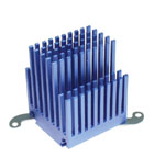
With them temperature was around 60C after more than 1 hour of operation and room temp was ~23C. So, looks very promising and I have to swallow my own words for being doubtful about the feasibility of using 2A3 valves.
With them temperature was around 60C after more than 1 hour of operation and room temp was ~23C. So, looks very promising and I have to swallow my own words for being doubtful about the feasibility of using 2A3 valves.
Hi,
It sounds maybe one of the CCS (Ixys 10M45) has thrown the towel, they do not like to see the output shorted to chassis.
Ciao T
I tried again. There is something wrong with one channel bias regulation. If I adjust left channel to 120V then the right one increases to 230V and it that voltage does not react on any of the right channel pot adjustment (from one extreme to another). If I make right channel to be around 120V then the left one drops to 40V. Both channels are sensitive to the left pot but so much to the right one. ANy ideas?
It sounds maybe one of the CCS (Ixys 10M45) has thrown the towel, they do not like to see the output shorted to chassis.
Ciao T
I just want to add that I managed to replace the heater voltage regulators. The old LM1084 from ebay were fakes. The new ones from element 14 work quite well with 2A3 valves and 0.33R resistors on the AC lines. Regulation is 100% stable at 2.5V. I installed these heatsinks by bonding them to the sides of the original ones by Arctic silver thermal epoxy
With them temperature was around 60C after more than 1 hour of operation and room temp was ~23C. So, looks very promising and I have to swallow my own words for being doubtful about the feasibility of using 2A3 valves.
This is very much in line with my experience based on my ''proof of concept'' with some aluminium bonded to the existing heat sinks. I have been running this set-up for several weeks now with 2a3 and there has been no unstability since then... It works
")
Hi,
It sounds maybe one of the CCS (Ixys 10M45) has thrown the towel, they do not like to see the output shorted to chassis.
Ciao T
That is what I was afraid of. Is there any chance that you or Brian can send me a pair of these. I cannot find them in element14 or RS catalogue and Digikey is not shipping them to Australia (manufacturers restrictions they say).
I appreciate your help.
Tram2 Operating Points
Hi,
I just joined the Tram2 family and would like to share some initial observations.
Initially I used TJ Globe 45s and WE 274B rectifier tubes as I happen to have them on hand. This setup works fine except for a low-level hum that I cannot get rid of. After some trouble-shooting I concluded the hum is generated by the amp itself and not due to other components or ground loops.
I also tried shielding the rectifier and the output triodes with a graphite tube shield connected to the signal input ground but no luck. Then I found a RCA 5U4 in my tube stash and tried it on replacing the WE 274B and voila the hum is gone completely.
So in this case the hum is either due to EM leak or different operating points resulting from the WE274B. To investigate this further I installed a UX4 test socket adapter to the TJ45 and measured:
- Filament voltage is 2.56V
- Bias current is 31mA (w/ 274B)
- Grid to filament ground is ~-8V (w/ 274B) and ~-10V (w/ 5u4)
- Plate to filament ground is ~80V (w/ 274B) and ~100V (w/ 5u4)
So it seems changing the rectifier could change the operating point of the output tubes. Is this normal? The RCA 5u4 does measured much stronger than the WE274B in my tube tester. Also, are the measured voltages/currents within spec? In particular is the plate-to-ground too low (~100V vs 120V)?
I also noticed that upon turn-on the plate-to-ground and grid-to-ground voltages are much higher, ~200V and ~-60V respectively, and then slowly converge to the values listed above.
One final question: do I need to adjust anything if I replace the 45 output tubes with 2A3? The manual seems to suggest it is plug and play but I want to make sure first.
Thanks.
Jack
- Status
- This old topic is closed. If you want to reopen this topic, contact a moderator using the "Report Post" button.
- Home
- DIY HiFi Supply
- DHT OTL Linestage - Tram 2