Hi,
Seems you only use the MC input.
Have a look if the MC inputs float or are grounded (100R//100nF will usually do this nicely).
Ciao T
Yes, I have two MC cartriges so I only use the MC input on The Vinyl Song.
Yes, the input is floating since it's the primary winding of the MC transformer. Or maybe you are referring to something else?
100R in parallel with 100nF..! Do you mean on the input of The Vinyl Song, on the primary side of the MC transformer? (sounds a bit strange..!!!)
Last edited:
Hi,
It looks to me like your wiring floats the primary completely, this can lead to hum.
Essentially Shell of MC RCA Input to the UTS Input ground via 100R/100nF (I call that "soft" ground), if this reduces hum but does not kill a direct wire may be needed.
Ciao T
100R in parallel with 100nF..! Do you mean on the input of The Vinyl Song, on the primary side of the MC transformer? (sounds a bit strange..!!!)
It looks to me like your wiring floats the primary completely, this can lead to hum.
Essentially Shell of MC RCA Input to the UTS Input ground via 100R/100nF (I call that "soft" ground), if this reduces hum but does not kill a direct wire may be needed.
Ciao T
OK, now I understand what you mean... You're suggesting either a ''soft'' or a ''hard'' ground between the input signal ground, and output signal ground on the mc transformer. Right?
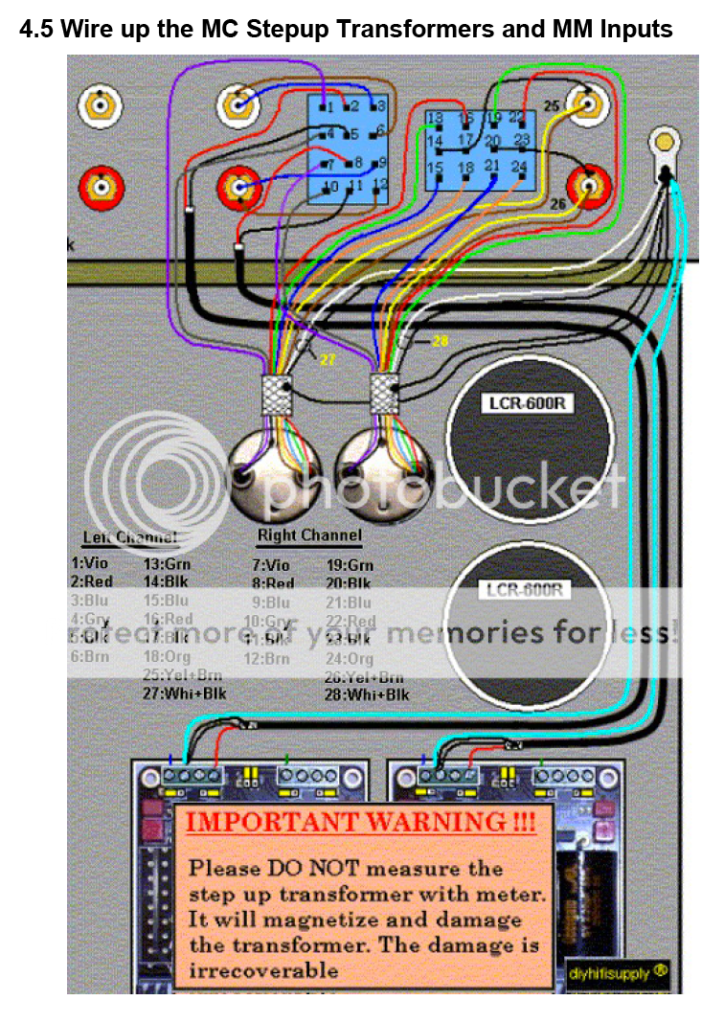
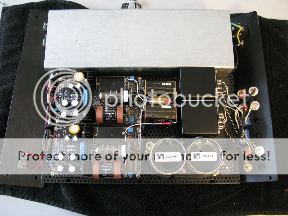
My wiring is done like this, from the build manual... The primary winding is indeed floating, and the screen (black wire) and housing (white wire) from the mc step-ups are connected to the ground post, as shown in the build manual.
I'm out of time working on this now, but next time I get some time I will try the ''soft'' ground, or even a direct connection. Thanks for these suggestions. I will get back with an update on the effect...
Last edited:
Hi,
Right.
Seeing this you can make the connections directly to the grounding post.
I also notice another chance for noise to get in. It looks like the Earth goes straight to the chassis. This I do not like.
Connect mains transformers screens directly to the IEC Earth, but connect a diode bridge (rated for the same current as the mains fuse or more) with +/- shorted together and using the AC pins between the IEC Earth connector and the Chassis.
The Diode bridge clamps any voltage between earth and chassis to around 2V. It may not pass on some "PAT" Testers, but it retains the electrical safety. Also connect 100R//100n between IEC Earth and chassis.
I normally prefer to connect bridge and RC between signal ground and chassis and have the chassis earthed, but that would mean isolating a lot of stuff from the chassis in the Vinyl Song and so cannot be done.
Ciao T
OK, now I understand what you mean... You're suggesting either a ''soft'' or a ''hard'' ground between the input signal ground, and output signal ground on the mc transformer. Right?
Right.
My wiring is done like this, from the build manual... The primary winding is indeed floating, and the screen (black wire) and housing (white wire) from the mc step-ups are connected to the ground post, as shown in the build manual.
Seeing this you can make the connections directly to the grounding post.
I also notice another chance for noise to get in. It looks like the Earth goes straight to the chassis. This I do not like.
Connect mains transformers screens directly to the IEC Earth, but connect a diode bridge (rated for the same current as the mains fuse or more) with +/- shorted together and using the AC pins between the IEC Earth connector and the Chassis.
The Diode bridge clamps any voltage between earth and chassis to around 2V. It may not pass on some "PAT" Testers, but it retains the electrical safety. Also connect 100R//100n between IEC Earth and chassis.
I normally prefer to connect bridge and RC between signal ground and chassis and have the chassis earthed, but that would mean isolating a lot of stuff from the chassis in the Vinyl Song and so cannot be done.
Ciao T
OK, time for an update on The Vinyl Song... During the Easter holidays I finally had the time to work on the hum issues, and I have found a solution that works.
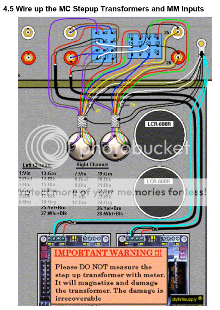
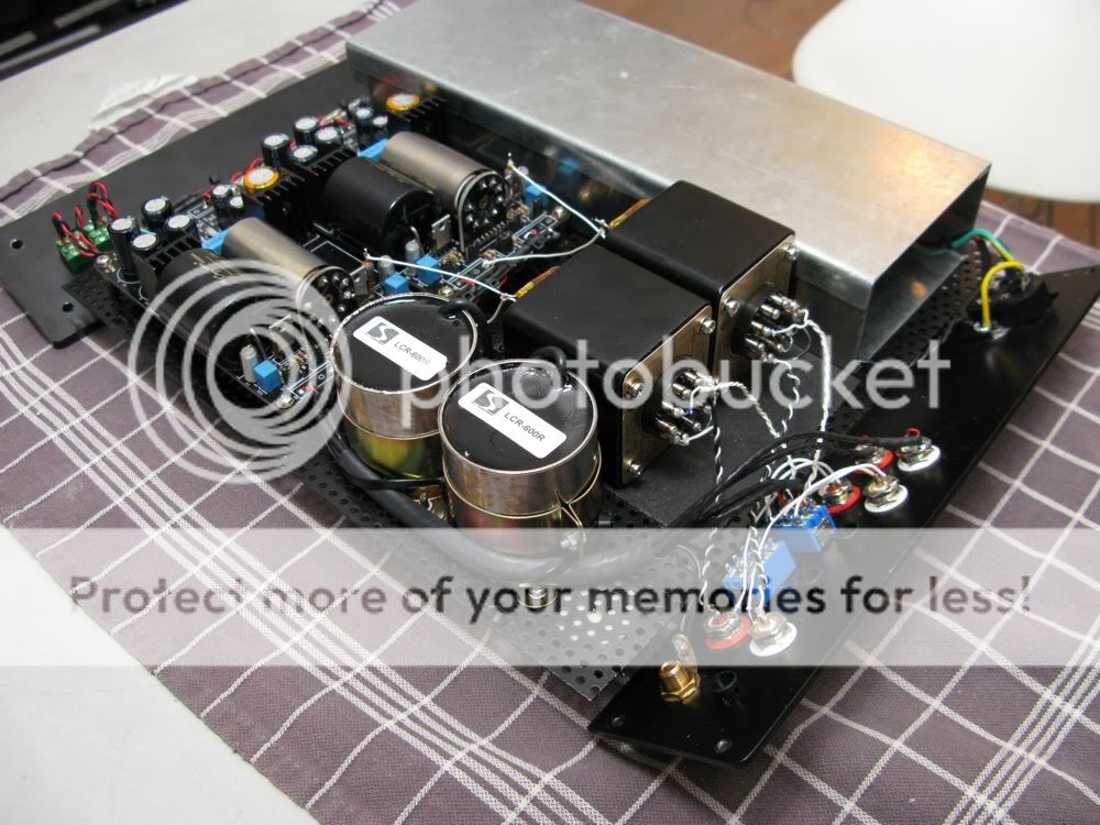
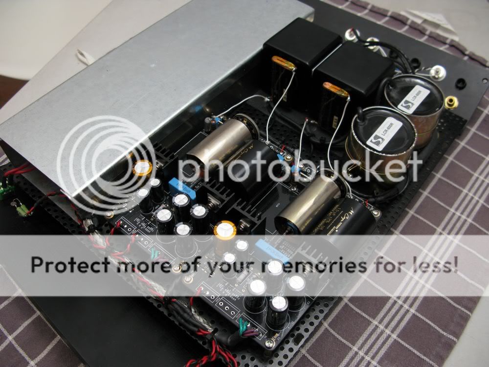
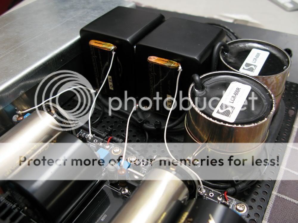
I have tried both ''soft ground'' and ''hard ground'' between the input ground and output ground for the mc step ups, the soft ground did not work here, but the hard ground did. The best way to implement this hard ground is to make a connection on the back plate switches as shown with the white lines on the attached picture. This way the ground is as close to the mc step-ups as possible and as far from the dirty chassis ground as possible. With this, there is just a slight bit of hum left, but barely audible. Maybe I'll try some of your other suggestions Thorsten to check if I can get rid of that also. But for now, this level of hum is more than acceptably low.
Also, when building this phono stage, please notice that the green/red and the blue/orange wires must be swapped for the switch to work as described in the manual.
Finally I recommend to have an individual screen on each wire pair, that way the screen can follow the wires all the way to the soldering points on the switches and connectors, this gives the lowest noise/hum level.
I'm running in the phono stage now. The first impression is, that the treble is quite splashy and forward, but I think that's normal for brand new step up transformers and LCR circuits.
Last edited:
Questions for you Thorsten, thanks for helping ")
After sorting the grounds my Vinyl Song is now singing without hum, and it sounds great. However it's also singing very quietly, there is not much gain..! As a comparison, I have the volume control on my Tram II at around 2 - 3 o clock when listening at loud levels with my cd player (2 volt output). I use the middle - 3dB output on the Tram. However, when listening to vinyl I can only get moderate levels even when turning the volume all the way up.
My cartridge is a Sumiko Pearwood Celebration II with 0,5mV output, so there is plenty of signal feeding The Vinyl Song, and I have of course tried both the ''hi'' and ''low'' gain settings.
I use a pair of NOS RCA ECC88 tubes.
So what is the gain actually in this phono stage? And is there a way to increase it?
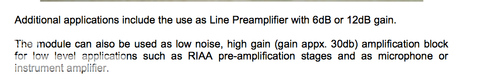
When looking in The Vinyl Song build manual these specs are mentioned, with these jumper settings:
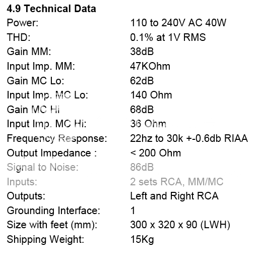
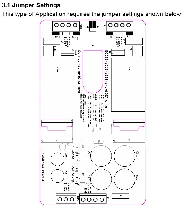
But when I then look in the specs mentioned for the Universal Tubestage used in The Vinyl Song the gain with this jumper setting is mentioned as 30dB. If this is the case, then the total gain in The Vinyl Song will be around 30dB in the MM setting and around 50dB in MC setting, meaning that I need around 10dB of gain. This makes sense compared to the low gain I have...
Here the specs from the Universal Tubestage:
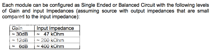
Can you please advise how to get the right gain (as mentioned in The Vinyl Song specs)?
Another question... Regarding the cartridge load.
I would like to implement a 24 position selector, located on the back panel, to give me more load options for the cartridge. This means that I need to increase the 47K input load resistor on the module to -lets say- 470K and then have one of the resistors on the 24 position selector in parallel with that resistor. This way I can get high resolution on the load of MC cartridges.
My question is: Can you help locate the 47K input resistors on the tube module that I need to replace?
Thanks again Thorsten!
Morten
After sorting the grounds my Vinyl Song is now singing without hum, and it sounds great. However it's also singing very quietly, there is not much gain..! As a comparison, I have the volume control on my Tram II at around 2 - 3 o clock when listening at loud levels with my cd player (2 volt output). I use the middle - 3dB output on the Tram. However, when listening to vinyl I can only get moderate levels even when turning the volume all the way up.
My cartridge is a Sumiko Pearwood Celebration II with 0,5mV output, so there is plenty of signal feeding The Vinyl Song, and I have of course tried both the ''hi'' and ''low'' gain settings.
I use a pair of NOS RCA ECC88 tubes.
So what is the gain actually in this phono stage? And is there a way to increase it?
When looking in The Vinyl Song build manual these specs are mentioned, with these jumper settings:
But when I then look in the specs mentioned for the Universal Tubestage used in The Vinyl Song the gain with this jumper setting is mentioned as 30dB. If this is the case, then the total gain in The Vinyl Song will be around 30dB in the MM setting and around 50dB in MC setting, meaning that I need around 10dB of gain. This makes sense compared to the low gain I have...
Here the specs from the Universal Tubestage:
Can you please advise how to get the right gain (as mentioned in The Vinyl Song specs)?
Another question... Regarding the cartridge load.
I would like to implement a 24 position selector, located on the back panel, to give me more load options for the cartridge. This means that I need to increase the 47K input load resistor on the module to -lets say- 470K and then have one of the resistors on the 24 position selector in parallel with that resistor. This way I can get high resolution on the load of MC cartridges.
My question is: Can you help locate the 47K input resistors on the tube module that I need to replace?
Thanks again Thorsten!
MortenMy cartridge is a Sumiko Pearwood Celebration II with 0,5mV output, so there is plenty of signal feeding The Vinyl Song, and I have of course tried both the ''hi'' and ''low'' gain settings.
I will try to help.
Are you using a step up transformer?
0,5mV output is not a high output MC cartridge and usually need a step up transformer.
The sumiko blue point special is a high output MC with 2.5mV of output.
BTW, if you need a step up transformer, you get a a nice one from Brian.
Raymond.
Thanks for your reply If you look back in this thread you will notice that I have the ''fully loaded'' Vinyl Song with the LCR modules and the MC step-ups.
For a low output MC the Sumiko Pearwood Celebration II output on 0,5mV is amongst the highest from any low output MC, but still the gain from this phonostage is very low...
If you look back in this thread you will notice that I have the ''fully loaded'' Vinyl Song with the LCR modules and the MC step-ups.For a low output MC the Sumiko Pearwood Celebration II output on 0,5mV is amongst the highest from any low output MC, but still the gain from this phonostage is very low...
Last edited:
A few updates...
The mc step up transformers replaced with a pair of Hashimoto HM-3, the polystyrene caps after the LCR modules replaced with 220nF Duelund VSF, the output caps are now Mundorf silver/gold and the wiring to/from step up's and LCR's is silver in silk. Also I did a bit more work on shielding with mu-metal inside the transformer box, and the result is, that the phono stage is really quiet...
The mc step up transformers replaced with a pair of Hashimoto HM-3, the polystyrene caps after the LCR modules replaced with 220nF Duelund VSF, the output caps are now Mundorf silver/gold and the wiring to/from step up's and LCR's is silver in silk. Also I did a bit more work on shielding with mu-metal inside the transformer box, and the result is, that the phono stage is really quiet...
Hi, how does the sound of the Hashimoto HM-3s compare with the Cinemags?
That's an intesting question
I don't know yet, just installed the Hashimoto's yesterday and I have only listened to test if my implementation is without hum (and it is).I'll get back with update when I have had the chance to break in the Hashimotos...
Hi, how does the sound of the Hashimoto HM-3s compare with the Cinemags?
Yes, I too like to know the comparison. Review please?
Hi, how does the sound of the Hashimoto HM-3s compare with the Cinemags?
Yes, I too like to know the comparison. Review please?
I picked up something excellent from your project, that is a copper shielding around the signal wires. I quickly dug up an old Canare i/c, stripped the excellent and thick copper shielding, spent the last hour doing what you did, and on test now. A quick cranking up the volume w/o signal impresses on me with lower noise floor. For now, I think its as quiet as can be. Excellent tip you've shared! I suppose every bit does help.
Its a Cinemag external box. Just shielded the input wires for now. SUT wires remain factory length and didn't shorten them to minimum required although some may disagree as not right during a build. Anyhow, its still within desirable performance and lowest noise achieved so far.
On another note, I've compared the Cinemag vs UTC A-11 numerous times, the Cinemag impress having more mid range presence and overall musicality.
I've no opportunity to audition any Hashimoto, keen to know.
Last edited:
Great..! and thanks for sharing
On The Vinyl Song it's difficult to make a good connection to/from the connectors and switches on the back because the back panel is connected to the top cover. Hence when the top is off the back panel is ''loose'' as seen in my pictures. This means that the wires needs to be quite flexible to allow for movement of the back panel.
First I tried to run the silk insulated silver wire inside a mesh screen, that was again inside a thin plastic tube (needed to prevent the shield to make shorts on the connectors and switches when the back panel is installed). But this was not flexible enough and put a lot of stress in the thin silver wires.
Instead I used the good old trick of making a twisted pair where one of the wires is used as screen. I used ordinary flexible copper hook up wire and it gives excellent screening. Just remember just to connect at one end only. If you look at my pics you will notice that the black (shield) wire is not connected at the RCA end.
If you look at my pics you will notice that the black (shield) wire is not connected at the RCA end.
Agreed, thats a very important point for shielding. In my case, the Cinemag black, white, new shield wires are all directly terminated at the box ground lug. No contact with the box or RCA jacks. The two cans are permanently bolted upright (body direct contact with box) to the box. The ground lug is isolated and no electrical contact with the box. An external wire connects this lug to the active phono stage. The ground lug can easily be bolted on with or without box contact. Its technically an approved UK branded binding post made with external plastic. The same type used in my active phono stage.
An added implementation whether it made any difference, was to solder a piece of 100pF polystyrene caps at the SUT output jacks. All capacitor optional loading at the active phono stage is switched off by implemented dip switch. I felt nearest and direct loading at the output jack was best.
I've included an earth lift switch which shorts the RCA jack outer terminal to the ground lug. This is necessary for compatibility with stock Rega tonearm which is my other TT.
Since I'm with MC cartridge indefinitely , I believe it works best with all external cabling be 2 wire shielded mic cable up to the active phono stage and line level(using canare L2T2S) with the shield grounded at the TT chassis and others at one point. Never looked back since. For years, always thought any good audio grade interconnect would do, learnt much later its not always the case with MC, just have to go the extra mile with shielded cable. (echoing from someone in Audio Asylum who also realized this). Proper grounding techniques is so important and lift its performance.
Another matter which I realized, SUT size does matter. I happen to have those Beyerdynamic peanut sized SUT. They just don't offer the more wholesome and bigger bodied sound of the Cinemags. Output volume seemed much lower too but thats not a high issue. Amazingly the UTC and Cinemag very similar sonic dimensions despite its vast different in physical size. No more wanting peanuts
Last edited:
Final update to The Vinyl Song LCR...
The only thing that I have been missing with this phono stage compared to what I have owned before is the possibility to easy adjustments of the loading of MC cartridges. So I have made this What I have now is 23 steps of loading in the range of 7 ohm and 70 ohm on the cartridge. This is with the Hashimoto step up's in the 1:40 ratio. The lower end of the loading range match my Ortofon MC 70 Anniversary and the higher range match my VDH Canary.
I did not want to compromise sonic, so I wanted short wires and good resistors for this. The solution is, that I have located the switch just next to the inputs of the circuit boards and the knob out the bottom. This gives relatively easy access to the know and the shortest possible wiring. I have used Shinkoh tantalium as the resistor on the RIAA input and Takmann metal film resistors on the attenuator.
Flexibility with this phono stage is now as good as I need it to be
BTW... Also installed a pair of Jupiter Beeswax HT to try them out. I hear good things of them, and that they should have a very natural and spacious sound. I would love to use Duelund here also, but there is no room...


The only thing that I have been missing with this phono stage compared to what I have owned before is the possibility to easy adjustments of the loading of MC cartridges. So I have made this
What I have now is 23 steps of loading in the range of 7 ohm and 70 ohm on the cartridge. This is with the Hashimoto step up's in the 1:40 ratio. The lower end of the loading range match my Ortofon MC 70 Anniversary and the higher range match my VDH Canary.I did not want to compromise sonic, so I wanted short wires and good resistors for this. The solution is, that I have located the switch just next to the inputs of the circuit boards and the knob out the bottom. This gives relatively easy access to the know and the shortest possible wiring. I have used Shinkoh tantalium as the resistor on the RIAA input and Takmann metal film resistors on the attenuator.
Flexibility with this phono stage is now as good as I need it to be
BTW... Also installed a pair of Jupiter Beeswax HT to try them out. I hear good things of them, and that they should have a very natural and spacious sound. I would love to use Duelund here also, but there is no room...
Last edited:
Hi,
I have to dig out this old thread and hope that someone is still tracking it ;-)
I have just finished the kit (after some issues - wrong tubes supplied + resistors on the PCB interchanged). The sound is great - however I got some hum. As I only use MM this should not happen. I plan now to rebuilt the kit in a bigger cabinet (the supplied one is totally unpractical) and to use a custom made torroid. I also intend to switch both of the big caps , the one on the PCB (2,2 uF) and the other which is soldered on the lugs (0,68 uF). Desmo used different values for those so my question is if the 2 caps are not crucial for the phono equalisation. The 2,2 uF I am shure it is not, but with the 0,68 uF I am not really sure if this is also just a coupling cap.
I hope that someone can help.
Thanks
Peter
- Status
- This old topic is closed. If you want to reopen this topic, contact a moderator using the "Report Post" button.
- Home
- DIY HiFi Supply
- LCR Phono the EZ Way - Vinyl Song