DIY HiFi Supply Preamplifier Control System Introduction:
This Preamplifier Control System uses an electronic potentiometer as used in all current Audio Research Preamplifiers, unlike other common volume control chips this device does not contain a build in op-amp. The Preamplifier Control System consists of two PCBs:
Audio PCB:
1. 2 channels
2. 5-way input switching, and
3. Volume control, can be configured as mono balanced or stereo single ended
Control PCB:
1. ALPS rotary encoders
2. LED indication of input & volume, and
3. Power-supplies and microprocessor control
Features:
127 step volume control from -52dB to 0dB attenuation with 12 LED level indicators
5 Inputs with LED indicators
Remote control via universal remote control (RC5 code)
Options for shunt operation (-46dB to -3dB or -52dB to -6dB)
5 way Silver alloy relay input switching
LED’s driven on/off, not “multiplexed” to remove digital noise
Audio PCB includes option for fitting two LSK389B Zero FeedBack J-Fet buffer (direct coupled – no coupling capacitors) to make a stand alone buffered passive preamplifier with <50Ohm Output Impedance
Control PCB delivered as one PCB but allows “break-off” of the rotary encoder & LED parts (connection via 20-Pin IDC cables (supplied)
Control PCB can control up to 3 Audio PCB’s (6 channels single ended or 3 channels balanced); with optional transformer can control up to 8 Audio PCB’s (16 channels single ended or 8 channels balanced)
Control PCB connects to Audio PCB via 20-Pin IDC cables (supplied)
Power Supply using schottky diodes and low noise regulators
Torroidal mains transformer with 115/230V Primary capable of supporting 3 Audio PCB’s with buffer fitted included
Mains transformer with 115/230V Primary capable of supporting 3 Audio PCB’s with buffer fitted included
Gold plated, 70 micron Copper PCB’s
Includes drill template (PDF for printing on paper) for drilling front panels for LED's, encoders and fittings
Audio board:
This board handles the audio signal and is fully DC coupled in/out and, since it's functions are self contained, can be positioned optimally close to signal I/O . There are:
* 5 INPUTS
* REC. can also be used as a direct in (ie single source). More about this later.
* DIRECT OUT which has an output impedance of 25Kohms
* JFET OUT which uses the optional JFET (LSK389-A) devices as shown installed and has an output impedance of 50 ohms
To use as a volume control in your amp or preamp just route all signal to the audio board and use the direct out connector block. EZ drop in to replace your existing attenuator.
But there is also a possibility to build a simple standalone linestage by using the JFET outs.
For example:
* Projekt chassis 240mm is perfect (we will be offering a premounted faceplate for the Ultimate VC)
* handful of RCA jacks
* Ultimate VC System with JFET option
Now you have a fully DC coupled, 50 ohm output impedance, unity gain linestage which has NONE of the problems of passive linestages. To paraphrase one of the masters: Sort of a like a 21st century Aunt Corey's Passive Preamplifier
We are doing a buildup of this now and will blog it shortly
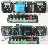
Controller board:
The Control Board is the long one shown; front and back. The short board is the audio board in the previous post.
We refer to the Control Board as the Control Matrix because it is actually 3 modules -- Volume, Selector, Logic/PSU -- which can be snapped off and positioned to suit any size faceplate (the Volume and Selector modules communicate with the Logic Module through ribbon connectors). Or it can be mounted as one unit to a suitably sized faceplate. The 240mm Projekt chassis happens to be one that is.
The center module contains the Logic and the PSU. Note: no extra transformer is needed; as you can see, it is in place on the module and ready to be connected to either 115 or 230v mains. Signal stays on the Audio Board; the Control Matrix is programmed to do all the switching and housekeeping and through a ribbon cable tells the Audio Board what to do with the signal.
The selector and attenuator switches have a shaft which allows a knob and manual control from the front panel -- or remote control using standard RC5 encoding.
The blue LED are meant to be visible through the faceplate and a drilling template is provided. The selector module has 5 LED installed -- one for each input. The Volume Control Module has 12 LED installed BUT there are actually 127 steps! We didn't think you would want to drill 127 holes for 127 LED.
Native attenuation is -52db to 0db from a reference 3.5V rms. But you horn guys are going to love this: Shunt mode allows -66db to -15db!
DIY Done Right!
This Preamplifier Control System uses an electronic potentiometer as used in all current Audio Research Preamplifiers, unlike other common volume control chips this device does not contain a build in op-amp. The Preamplifier Control System consists of two PCBs:
Audio PCB:
1. 2 channels
2. 5-way input switching, and
3. Volume control, can be configured as mono balanced or stereo single ended
Control PCB:
1. ALPS rotary encoders
2. LED indication of input & volume, and
3. Power-supplies and microprocessor control
Features:
127 step volume control from -52dB to 0dB attenuation with 12 LED level indicators
5 Inputs with LED indicators
Remote control via universal remote control (RC5 code)
Options for shunt operation (-46dB to -3dB or -52dB to -6dB)
5 way Silver alloy relay input switching
LED’s driven on/off, not “multiplexed” to remove digital noise
Audio PCB includes option for fitting two LSK389B Zero FeedBack J-Fet buffer (direct coupled – no coupling capacitors) to make a stand alone buffered passive preamplifier with <50Ohm Output Impedance
Control PCB delivered as one PCB but allows “break-off” of the rotary encoder & LED parts (connection via 20-Pin IDC cables (supplied)
Control PCB can control up to 3 Audio PCB’s (6 channels single ended or 3 channels balanced); with optional transformer can control up to 8 Audio PCB’s (16 channels single ended or 8 channels balanced)
Control PCB connects to Audio PCB via 20-Pin IDC cables (supplied)
Power Supply using schottky diodes and low noise regulators
Torroidal mains transformer with 115/230V Primary capable of supporting 3 Audio PCB’s with buffer fitted included
Mains transformer with 115/230V Primary capable of supporting 3 Audio PCB’s with buffer fitted included
Gold plated, 70 micron Copper PCB’s
Includes drill template (PDF for printing on paper) for drilling front panels for LED's, encoders and fittings
Audio board:
This board handles the audio signal and is fully DC coupled in/out and, since it's functions are self contained, can be positioned optimally close to signal I/O . There are:
* 5 INPUTS
* REC. can also be used as a direct in (ie single source). More about this later.
* DIRECT OUT which has an output impedance of 25Kohms
* JFET OUT which uses the optional JFET (LSK389-A) devices as shown installed and has an output impedance of 50 ohms
To use as a volume control in your amp or preamp just route all signal to the audio board and use the direct out connector block. EZ drop in to replace your existing attenuator.
But there is also a possibility to build a simple standalone linestage by using the JFET outs.
For example:
* Projekt chassis 240mm is perfect (we will be offering a premounted faceplate for the Ultimate VC)
* handful of RCA jacks
* Ultimate VC System with JFET option
Now you have a fully DC coupled, 50 ohm output impedance, unity gain linestage which has NONE of the problems of passive linestages. To paraphrase one of the masters: Sort of a like a 21st century Aunt Corey's Passive Preamplifier
We are doing a buildup of this now and will blog it shortly
Controller board:
The Control Board is the long one shown; front and back. The short board is the audio board in the previous post.
We refer to the Control Board as the Control Matrix because it is actually 3 modules -- Volume, Selector, Logic/PSU -- which can be snapped off and positioned to suit any size faceplate (the Volume and Selector modules communicate with the Logic Module through ribbon connectors). Or it can be mounted as one unit to a suitably sized faceplate. The 240mm Projekt chassis happens to be one that is.
The center module contains the Logic and the PSU. Note: no extra transformer is needed; as you can see, it is in place on the module and ready to be connected to either 115 or 230v mains. Signal stays on the Audio Board; the Control Matrix is programmed to do all the switching and housekeeping and through a ribbon cable tells the Audio Board what to do with the signal.
The selector and attenuator switches have a shaft which allows a knob and manual control from the front panel -- or remote control using standard RC5 encoding.
The blue LED are meant to be visible through the faceplate and a drilling template is provided. The selector module has 5 LED installed -- one for each input. The Volume Control Module has 12 LED installed BUT there are actually 127 steps! We didn't think you would want to drill 127 holes for 127 LED.
Native attenuation is -52db to 0db from a reference 3.5V rms. But you horn guys are going to love this: Shunt mode allows -66db to -15db!
DIY Done Right!
Attachments
When Is Ultimate EZ?
Now.
Check this out:
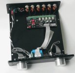
at the front we have the controls and the power supply. All the digital bits flow across those ribbons to selector (left), volume (right) and the audio signal board (chassis back).
The audio signal board uses end-to-end analogue potentiometers to adjust volume and vacuum silver relays to select source. The great thing is the audio signal board can be mounted beside the I/O jacks and the power supply can be put far away. This minimizes noise and maximizes musical fidelity.
Quiet it is. Next week I'll report some measurements.
Now notice the 2 little round circles with roach-like occupants, flanking the 2 red caps on the audio board. Those are the LSK389 JFET so that the JFetted outputs can drive any load (Zout 50 ohms!). But, these can be bypassed with the direct out connection going to another set of outputs. You'd want to keep the cables very short if used direct out.
EZ.
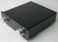
We will also offer a CNC'd front plate just like you see to premount the Control matrix board (the one attached to the knobs) to be used with your own chassis.
EZ'r.
Now how about those 127 steps? It's the first time we've ever had a device with 127 step attenuation. It's like having 5.5 x 23 step volume controls. What's it like to use? Jailbreak! Really. It's like the difference between looking at the world through prison bars or looking out a panoramic window.
And the sound: surprisingly smooth. Why surprisingly? Because it ain't got tubes! But it is passing along 100% of the tube-sound upstream.
More.
Now.
Check this out:
at the front we have the controls and the power supply. All the digital bits flow across those ribbons to selector (left), volume (right) and the audio signal board (chassis back).
The audio signal board uses end-to-end analogue potentiometers to adjust volume and vacuum silver relays to select source. The great thing is the audio signal board can be mounted beside the I/O jacks and the power supply can be put far away. This minimizes noise and maximizes musical fidelity.
Quiet it is. Next week I'll report some measurements.
Now notice the 2 little round circles with roach-like occupants, flanking the 2 red caps on the audio board. Those are the LSK389 JFET so that the JFetted outputs can drive any load (Zout 50 ohms!). But, these can be bypassed with the direct out connection going to another set of outputs. You'd want to keep the cables very short if used direct out.
EZ.
We will also offer a CNC'd front plate just like you see to premount the Control matrix board (the one attached to the knobs) to be used with your own chassis.
EZ'r.
Now how about those 127 steps? It's the first time we've ever had a device with 127 step attenuation. It's like having 5.5 x 23 step volume controls. What's it like to use? Jailbreak! Really. It's like the difference between looking at the world through prison bars or looking out a panoramic window.
And the sound: surprisingly smooth. Why surprisingly? Because it ain't got tubes! But it is passing along 100% of the tube-sound upstream.
More.
Attachments
Re: Ultimate Volume Control System - Features
Could be possibile to use only the volume section of this kit to use in a tube preamp? Maybe plus the input too?
bcherry said:DIY HiFi Supply Preamplifier Control System Introduction:
Could be possibile to use only the volume section of this kit to use in a tube preamp? Maybe plus the input too?
Re: When Is Ultimate EZ?
can we buy that chassis from you?
-joe
bcherry said:Now.
Check this out:
at the front we have the controls and the power supply. All the digital bits flow across those ribbons to selector (left), volume (right) and the audio signal board (chassis back).
The audio signal board uses end-to-end analogue potentiometers to adjust volume and vacuum silver relays to select source. The great thing is the audio signal board can be mounted beside the I/O jacks and the power supply can be put far away. This minimizes noise and maximizes musical fidelity.
Quiet it is. Next week I'll report some measurements.
Now notice the 2 little round circles with roach-like occupants, flanking the 2 red caps on the audio board. Those are the LSK389 JFET so that the JFetted outputs can drive any load (Zout 50 ohms!). But, these can be bypassed with the direct out connection going to another set of outputs. You'd want to keep the cables very short if used direct out.
EZ.
We will also offer a CNC'd front plate just like you see to premount the Control matrix board (the one attached to the knobs) to be used with your own chassis.
EZ'r.
Now how about those 127 steps? It's the first time we've ever had a device with 127 step attenuation. It's like having 5.5 x 23 step volume controls. What's it like to use? Jailbreak! Really. It's like the difference between looking at the world through prison bars or looking out a panoramic window.
And the sound: surprisingly smooth. Why surprisingly? Because it ain't got tubes! But it is passing along 100% of the tube-sound upstream.
More.
can we buy that chassis from you?
-joe
Could be possibile to use only the volume section of this kit to use in a tube preamp? Maybe plus the input too?
yes, there is a direct in connector block which bypasses the selector. However as a minimum for function, one controller board (contains the PS and logic) and one audio board is needed.
can we buy that chassis from you?
yes, that's the Projekt chassis set and comes in 3 sizes:
Projekt Chassis and Parts
All the Projekt parts are listed on that page.

June 23 happenins
Ultimate VC:
Quite a few have come through and listened and 100% unanimous: Ultimate VC = good sound!
I would characterize this as a very smooth, effortless sound, with no holding back.
On the Bench
our test equipment is 24bit/192khz. The Ultimate VC pushes our measurement abilities to the limit (JFET output into 10k load):
non-inverting phase
20hz - 80khz at -0.5db
THD: 0.007%
Dynamic range: 100.7 db
IMD + noise: 0.0076%
Our next step is to install the UTS in the same chassis together with the Ultimate VC
It seems everyone is ordering these with pre-drilled faceplates. I should have these in hand in 10 days.
UTS Phono stage:
the Cinemag stepup transformers arrived today and we will be offering the UTS phono with stepup transformer option. These are friendly little critters, nice and compact in their MU-metal cans.
Should have something to report on that by next week.
OK!
Attachments
LDR Hot Wired
Hot wired an LDR module onto the front end of UTS linestage. It's the top centre module. LDR uses attenuated light to control a light sensitive potentiometer. The little device at the end of the extension shaft is doing that job.
We getting our 5v from the BIX turntable motor controller but I think we can take it from the UTS power supply too.
One problem is LDR are limited in the level of attenuation so we've implemented relay to mute output when completely turned down. These are matched to 0.5db with 4 pcs LDR for stereo channels.
They need 5-6vdc to power the module and an external pot to control the illumination level.
One module + pot +5vDC can be used in place of a typical potentiometer.
Will report more as we go.
Have a good weekend.
Ultimate Volume Control + Universal Tube Stage
When has so much ever been so EZ? The Ultimate Volume Control system together with the Universal Tube Stage in a Projekt box.
UVC running in shunt mode driving the Universal Tube Stage set for 12db gain.
All fits together in the 240mm Projekt chassis and makes for a great active linestage with no noise, only music.
Faceplate for Ultimate Volume Control
We have them now. This makes life a whole lot easier as drilling 36 holes without a spoiler ain't easy (experience speaking here).
Comes with 4 gold plated mounting bolts and could be easily mounted to the side panels of your choice. Or just buy a Projekt box, in which case it bolts in place.

We have them now. This makes life a whole lot easier as drilling 36 holes without a spoiler ain't easy (experience speaking here).
Comes with 4 gold plated mounting bolts and could be easily mounted to the side panels of your choice. Or just buy a Projekt box, in which case it bolts in place.
Yes up to 3 audio boards (6 channels) with JFET outputs can be driven from one controller board/PS.Is it possible to set your volume control for 6 channels?
Daisy chaining capability is already built in.
regards
Brian
Banned
Joined 2002
Does the UVC provide the equivalent of a 3-terminal potentiometer at its terminals? I have an application that needs 6 ganged linear 100Kohm pots like the attached diagram (one channel shown). I could scale the component values to match other values of potentiometer resistance.
Attachments
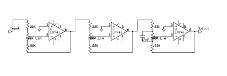
Hi Don,Does the UVC provide the equivalent of a 3-terminal potentiometer at its terminals? I have an application that needs 6 ganged linear 100Kohm pots like the attached diagram (one channel shown). I could scale the component values to match other values of potentiometer resistance.
This application is not possible, the lower end of the pot is grounded in the PCB and cannot be easily modified (not just "cut a trace").
Sorry
looks very interesting, clean and simple.!
Hello to Nanaimo. I think I can see you across the water. At the moment in Sechelt visiting my mother.
regards
Brian
Banned
Joined 2002
Hello to Nanaimo. I think I can see you across the water. At the moment in Sechelt visiting my mother.
regards
Brian
i wish i had known that, would have asked you to bring some demo product for testing
")
Yes it is listed under audio board here.is the extra input board available on the web site?
-joe
regards
Brian
- Status
- This old topic is closed. If you want to reopen this topic, contact a moderator using the "Report Post" button.
- Home
- DIY HiFi Supply
- Ultimate Volume Control