Hi,
I'm currently designing a true digital audio power amplifier for a school project. The digital part is almost done and I use a sigma-delta modulator to create a pwm one-bit output in an fpga. At first I thought the analog part was going to be easy but....obviously, it is not. I'm more specialised in dsp so the analog design is not really in my scope. I need help from the analog gurus here!!
The one-bit output from the fpga has to be 'amplified' to say -10V to 10V and it switches at about 300khz (pulse repetition frequency). A mosfet h-bridge is the best thing to use (from what I've read everywhere). The power supply seems to be tricky to design also.
The question is: where do you find an H-bridge that is well suited for audio?
- First, is it worth considering to build the bridge with discrete part? I heard that this could cause a lot of problems (thermal protection, cross talk ...).
- Second, are there some ICs that would do the job?
TI has a lot of documentation on digital amplifiers with Equibit technology. Here is their output stage IC,
http://focus.ti.com/docs/prod/productfolder.jhtml?genericPartNumber=TAS5110&pfsection=desc
However, I really don't understand how this chip works as it seems to require the use of their pwm proccessor IC(not sure on that). Does anyone knows if/how their output stage could be used with another pwm generator?
Apart from TI, does anyone know if there are some good h-bridge IC's or any other high quality class D output stage design somewhere?
As for the reconstruction filter, TI's documentation is pretty clear so it should not be a problem to figure out what needs to be designed.
Thank you very much
Gretz
Hi Gretzteam
Have a look at IRF (www.irf.com) they have a lot of mosfet driver ICs.
Motorola AN1042 contains a simple drive circuit for a complementary PWM output stage. It's downside is that it is AC coupled and may loose control for sustained on- or off- periods. There is however a simple solution to this problem. If you are interested in that I can give you details.
BTW: What order is your DS modulator ? Is this amp intended for low or mid frequencies only ? I ask this since I assume that your sampling frequency is about 600 kHz only.
Regards
Charles
Looks like you could use the Texas curcuit that you refered to if you create the signals that it needs. Wouldn't be too hard I think.
Otherwise you could make a discrete design. It's not that hard but there are a few problems that has to be solved. Using a drive circuit from IRF would simplify the construction.
How much power output have you specified? And what supply voltages?
/Marcus
Otherwise you could make a discrete design. It's not that hard but there are a few problems that has to be solved. Using a drive circuit from IRF would simplify the construction.
How much power output have you specified? And what supply voltages?
/Marcus
If this is your first switching amplifier then I say yes, because then you can be reasonably sure that this part of the cct won't give any trouble. The point is, the whole amp will be enough of a problem to get going satisfactorily and anything you can do to simplify the first cut will be beneficial. Later, when everything is running just right you can switchgretzteam said:- First, is it worth considering to build the bridge with discrete part?
 to a discrete output stage.
Hi,
another chips you might want to consider are STA500 and STA505 from ST and also Intersil driver chips HIP2100 and HIP4080 series. Intersil had app note about digital amplifier based on HIP4080. I would suggest not building discrete H bridge if this is your first design.
Another thing: When using H (full) bridge you need only positive supply voltage, there is no need to use +/- 10V, in fact all mentioned chips would not allow this.
regards
Jaka Racman
I have noticed that the National LM4651 datasheet shows an external chip (LM4652) that is driven by their Class D IC.
its at:
http://www.national.com/ds/LM/LM4651.pdf
its at:
http://www.national.com/ds/LM/LM4651.pdf
Hi,
Thanks for the info on the STA500 chip. It looks very good and a lot easier to use than TI's one.
Has anyone experienced with any of those chips? STA500, IRF2010, HIP2100? Which one gives best results? I'm not familiar with any of those manufacturers so I don't know who's the 'best'.
I'd like to get an amplifier of about 30W to 50W. This gives a supply voltage of around 20V which should not be to much trouble to build.
phase_accurate
I'd be really interested to hear about your work-around solution for the motorola application note. How would you compare their design with the chips mentionned above?
The amplifier is not intended for a subwoofer but for high quality audio (I hope!) I used a seventh order modulator with 64 times oversampling. That gives a 2.8MHz switching frequency but there are techniques to reduce it to about 350Khz without adding too much noise (bit-flipping algorithm). I'm confident that the modulator gives better result than TI's Equibit technology. The whole problem resides in building a very high quality output stage.
Any ideas are welcome
Gretzteam
Hi,
I used IRF2110 (500V driver) and HIP2100 and I have ordered STA500 for next job project. I presume you will not take feedback from output stage for your modulator and you will run output stage open loop, so you are looking for minimum pulse width distortion. I have no expirience with IRF2010 but IRF2110 works good for frequencies up to 200kHz. On the other hand, I had problems with some other IRF driver (can`t remember part number right now) where propagation delay was very much dependant of logic supply voltage. HIP2100 is the fastest half bridge driver of all and it also works good (I tried it at 400kHz). However, if you will use driver with discrete MOSFETs, you will face nontrivial problem with PCB layout and selection of proper MOSFETs (low gate charge, fast intrinsic diode). You will probably need 2 or 3 iterations of PCB layout to get satisfctory results. Regarding STA500 I will not use it before 3 months time. There is also no typcal propagation delay spec in the data sheet, but at least max is symmetrical. I have expirience with some other ST chips and they do deliver what they claim. IRF and Intesil are also good firms, but IRF`s MOSFETS are better than it`s chips. I pesonally would go with STA500, and study all available data about TAS5100 series regarding PCB layout and decoupling. (I am not sure if ST has any application notes out yet).
Regards,
Jaka Racman
Nowadays I would go for an IRF2110 (or something with similar functionality but I have no experience with it's competitors)because of simplicity and the possibility to use two N-channel FETs.
I have compared it's data sheets from twelve years ago and today and it has definitely been improved.
One problem with this IC is the possibility of latchup for extended on-time of the upper MOSFET (will happen with other half-bridge drivers as well!). But there are workarounds for this problem. With a symmetric PSU you will also need a level shifting circuit between modulator and the driver's logic inputs, but this isn't complicated either.
Back then we wanted a fast and cheap gate drive solution, so we decided to use something like the Motorola circuit but this definitely had to be improved.
For small output voltages there are enough P-channel MOSFETS available with low rdson so there was no need for a N-channel only solution.
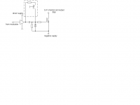
Instead of using two small discret MOSFETS we used a dedicated gate driver IC (TSC427, it's successor is now manufactured by IRF as well). Below you see the drawing of the lower half of the circuit. The part in the box is the additional DC path that enables infinite on- or off- times (we designed it for a DC current of 2 mA approx).
Regards
Charles
I have compared it's data sheets from twelve years ago and today and it has definitely been improved.
One problem with this IC is the possibility of latchup for extended on-time of the upper MOSFET (will happen with other half-bridge drivers as well!). But there are workarounds for this problem. With a symmetric PSU you will also need a level shifting circuit between modulator and the driver's logic inputs, but this isn't complicated either.
Back then we wanted a fast and cheap gate drive solution, so we decided to use something like the Motorola circuit but this definitely had to be improved.
For small output voltages there are enough P-channel MOSFETS available with low rdson so there was no need for a N-channel only solution.
Instead of using two small discret MOSFETS we used a dedicated gate driver IC (TSC427, it's successor is now manufactured by IRF as well). Below you see the drawing of the lower half of the circuit. The part in the box is the additional DC path that enables infinite on- or off- times (we designed it for a DC current of 2 mA approx).
Regards
Charles
Attachments
Hi There!
I'm kinda new to this pwm stuff and I would like to know the difference between the mosfet driver and the mosfet bridge. I think that Grezteam already has his PWM wave coming out of the fpga and he wants to drive the H-bridge with it. If this is the case, then why use a separate driver between his modulator and the H-bridge?
Thanks
SpeedWheel
Having read all those datasheet carefully, I think I'll go with the STA500. It looks like it's the best chip out there suited for hi-end audio.
Jaka Racman:
However, there is a big problem: Every distributor listed on the ST website are out of stock for something like 14 weeks. Since all this is for my final year electrical engineering design project which is due in 4 months, I really need a couple of those STA500 fast! You said you already ordered the chips but won't start working with them for 3 months. If you already have the chips and would be willing to sell me one or two, let me know...you're my last chance!
On another topic, I'd like to know what you guys think of the power supply described here:
http://www.apogeeddx.com/power.pdf
Does anyone know other design worth considering or it would be better to start from scratch?
This company seems to sell very good ICs for digital amplification. Their output stage seems pretty good to, but they use three states (1 0 -1) at the output of the modulator to reduce the switching frequency. The bridge might have a hard time with a one-bit approach.
Again thanks everyone.
Gretzteam
Hi gretzteam,
I am sorry, but as already wrote I ordered those chips for my next job project, so it means they belong to the company I work for and not to me. I can however check with our import department where they ordered them. I seem to recall there was problem with minimum quantity which is around 36pcs(1 tube-packing unit). I will let you know on Monday.
Regarding Apogee power supply it might be a good starting point. Especially if you consider that ST is licensee for DDX technology and STA500 bridge is intended to work with DDX modulation. So you might also consider Apogee power stages.
I suggest you take a look at http://www.pulsus.co.kr/downlodwfile/ps9702b_solutions1.pdf. You will see you can get comparable results with almost any chip. Should you consider Texas chip (you can get free samples fast) I can try to help you to properly apply it.
Regards,
Jaka Racman
Thanks for the info on the ST chip. A pack of 36 would be simply too much for me at this time so I'll probably go with TI's chip. It took only 2 days to get the samples...
Apogee's technology uses three state at the output stage so I'd like to avoir their product since I only use two states.
Thanks for your help concerning the TI' chip. I'll carefully read the datasheet and come back here if I have any problem.
The big issue now is to design the power supply, choosing good transformer ratings, regulators, decoupling capacitors, etc...I'm lost a little here since the requirements are not the same as for regular audio amplifier psu where you can put 100 000uF per channel. I want to keep a good compromise between size, cost, quality and efficiency. TI is very clear on that, everything is in the power supply and proper layout.
Gretzteam
- Status
- This old topic is closed. If you want to reopen this topic, contact a moderator using the "Report Post" button.
- Home
- Source & Line
- Digital Source
- Help needed - H-bridge, ClassD output stage IC for digital amplifier