hi
Enybody built Lars Nielsen DAC?
http://home.worldonline.dk/hifiside/ecdafsp.htm
any comments?
best regards
Lenny
Enybody built Lars Nielsen DAC?
http://home.worldonline.dk/hifiside/ecdafsp.htm
any comments?
best regards
Lenny
I would be very tempted to build the Digital section, but to use the Pass Labs D-1- I/V and output stage. It would be a bit more complex but is much more advanced than Lars simple output stage is. Not to say his does not sound good...as I'm sure it does. I just like the stuff that Nelson does in general. I also find Lars power supplies a bit odd, and not the usual high end stuff. Perhaps those parts are easier for him to get in his location.....
I certainly do give him credit for putting it all together!
Mark
I certainly do give him credit for putting it all together!
Mark
I noticed the PCM1730 too. Looked like a very nice chip for a simple, small parts count DAC.
So I ordered the chips and got them yesterday. The PCM1730E is a SMD, a very, !very! small one. It looks too small to solder by hand. A good PCB might help. Does Lars Nielsen sell PCB's? I would be very interested.
The Lars Nielsen design looks good to me. The power supply is perfectly fine. These cap-multipliers have a PSSR of 70dB typical up to the MHz range. Very high frequency might be transmitted through the transistors CE capacitance. I figure you need a shunt regulator in series after a cap-multiplier to block that. That should give a PSSR of about 110dB up to 10's of MHz. For I/V I would use a discrete design just for fun.
Regards,
Thijs
PS
Although all specs are given for 24bit only, I would say that low level (-60dB) 16 bit performance might not be up to par. Does anybody know how this chip deals with 16bit data? Is it rescaled to fit 24 Bit data? Can we then convert the 24bit data diagrams to 16 bit performance diagrams by adding 50dB to the Y-axis?
Hi Elso,
I'll sure be interested in your opinion of this design. Do you know of any SMD SOIC to DIP adaptors for thios tiny tiny chip.
Regards,
Thijs
http://www.diyhifi.dk/projekt2.html
I'll sure be interested in your opinion of this design. Do you know of any SMD SOIC to DIP adaptors for thios tiny tiny chip.
Regards,
Thijs
http://www.diyhifi.dk/projekt2.html
Thanks!!
Hi Thijs, Thanks for the working link.
What can I say about about this DAC?.
To start with the powersupplies See the high speed diode thread for better alternatives for the 1N4001. Still wondering about the arrangement of the rectifiers...
The emittorfollower regulator is similar in basic design to my triple Darlington, but a simple zenerdiode looks crude..
Ask Joko about opamp as IV-converter")
Browndog has nice SOIC to DIP adapters
www.brndog.com
tschrama said:Hi Elso,
I'll sure be interested in your opinion of this design. Do you know of any SMD SOIC to DIP adaptors for thios tiny tiny chip.
Regards,
Thijs
http://www.diyhifi.dk/projekt2.html
Hi Thijs, Thanks for the working link.
What can I say about about this DAC?.
To start with the powersupplies See the high speed diode thread for better alternatives for the 1N4001. Still wondering about the arrangement of the rectifiers...
The emittorfollower regulator is similar in basic design to my triple Darlington, but a simple zenerdiode looks crude..
Ask Joko about opamp as IV-converter
Browndog has nice SOIC to DIP adapters
www.brndog.com
PCB
Hello,
there is a pcb on Lars site, but the dimensions of the bitmap are enlarged when we take the *.bmp.
http://www.diyhifi.dk/layout1.html
There is this comment but I don't speak this language ?
"For at sikre optimal billedkvalitet, er printlayout og komponentplacering præsenteret i fuld opløsning.
Brug printerens zoom funktion for at tilpasse størrelsen efter målebåndet på 50mm. En god kopimaskine
kan også bruges til at justere størrelsen."
Pascal.
Re: PCB
I don't speak the the language either but what I make of it sounds like:
For a optimal image quality of the printlayout and component placement I found following solution:
Use the printers zoom function ..............................50mm [probably using some fixed measure pasted or glued into the layout to reference to]
You can use every good copy (Xerox) machine to adjust to the right scale...
 I hope I am not too far off.
Next month I have to practice Greek (holiday), Oh boy that's a different piece of cake ........
Salutations cordiales ,
(That's French by the way)
Hi Pascal ,PTSOUNDLAB said:Hello,
there is a pcb on Lars site, but the dimensions of the bitmap are enlarged when we take the *.bmp.
http://www.diyhifi.dk/layout1.html
There is this comment but I don't speak this language ?
"For at sikre optimal billedkvalitet, er printlayout og komponentplacering præsenteret i fuld opløsning.
Brug printerens zoom funktion for at tilpasse størrelsen efter målebåndet på 50mm. En god kopimaskine
kan også bruges til at justere størrelsen."
Pascal.
I don't speak the the language either but what I make of it sounds like:
For a optimal image quality of the printlayout and component placement I found following solution:
Use the printers zoom function ..............................50mm [probably using some fixed measure pasted or glued into the layout to reference to]
You can use every good copy (Xerox) machine to adjust to the right scale...
I hope I am not too far off.Next month I have to practice Greek (holiday), Oh boy that's a different piece of cake ........
Salutations cordiales ,
(That's French by the way)
Re: PCB
Hi Pascal.
I mailed the schematics yesterday,
Bonne nuit........
PTSOUNDLAB said:Thank you Elso,
have you received my postal mail for dac schematic ?
Cordialement (like "salutation cordiales" in french
Pascal.
Hi Pascal.
I mailed the schematics yesterday,
Bonne nuit........
PCB on Lars's site
Hi
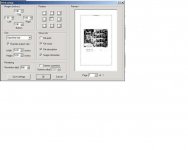
I made the pcb yesterday. Here's how I did it.
Save the layout pictures. In AcdSee you set the picture to specified size. With a 300 dpi resolution the size is 6.20 x 6.20.
With 600 dpi it's 5.20 x 5.20.
Worked fine on a 2 different HP printers.
/Henrik
P.S.
I find the pcb pattern a little to tight for home making. Hope to get some comments from you guys
Hi
I made the pcb yesterday. Here's how I did it.
Save the layout pictures. In AcdSee you set the picture to specified size. With a 300 dpi resolution the size is 6.20 x 6.20.
With 600 dpi it's 5.20 x 5.20.
Worked fine on a 2 different HP printers.
/Henrik
P.S.
I find the pcb pattern a little to tight for home making. Hope to get some comments from you guys
- Status
- This old topic is closed. If you want to reopen this topic, contact a moderator using the "Report Post" button.
- Home
- Source & Line
- Digital Source
- Lars Nielsen DAC, comments?