denon clock mod
Hi Pmd_audio, I have had my denon 500 for years now, and I read about the mods one can do on this machine.
I would like to start with the clock mod, but it is not really clear t me where to connect the parts to the board. I have seen the photo's of you and of someone else on this site, but the pictures reveals the connection to the board.
Can you help me?
Paul
All is much worse, misters!
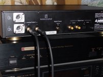
For the information - at comparison Parasound D/AC-1000 and D/AC-1500 the signal passed{took place} both through 1500, and through 1000 differences not noticeably absolutely!
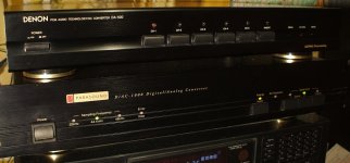
I recently have got DA-500. Has involved presence of many inputs. Too thought to make updating because assumed, that it{he} will sound certainly worse, than mine Parasound D/AC-1000. But when has compared - the difference has turned me into a shock. At testing it was found out - DA-500 is murderer SP/DIF of a signal! At passage of a signal through DA-500 Parasound sounds approximately so as DA-500! It means, that signal SP/DIF is deformed{distorted} already in entrance circuits-комутаторах DA-500! And updating of hours, a power unit, and other updatings is as at Russian speak " Catching of fleas "! The Reason of a bad sound - bad entrance schemes{plans} and elements.The simple clock mod with one diode+cap works well in my modded DA500.
For the information - at comparison Parasound D/AC-1000 and D/AC-1500 the signal passed{took place} both through 1500, and through 1000 differences not noticeably absolutely!
Attachments
I'm not saying that clock being distorted. I say that the input circuits make such distortions that the modification of clock will not give good results. First, you need to modify the input circuit, then all the rest.The simple clock mod is there to prevent the entrance circuit from clock distortions.
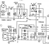
Sry for my misunderstandable reply. Here's a more untwisted sentence: The clock mod is there to disable the clock from the entrance circuit when it's not more needed (it's only needed for triggering to an incoming new data stream). Without the mod, the entrance circuit will be disturbed by the (additional) working clock (it's described in this thread before, read it from the beginning!). The entrance circuit (input receiver chip ym3626b) outputs also the spdif stream, so output can be disturbed when the ym3623b gets clock signals when it's already locked to the data stream.
Last edited:
The simple clock mod is there to prevent the entrance circuit from clock distortions
Sry for my misunderstandable reply. Here's a more understandable version (?): The clock mod is there to disable the external clock from the entrance circuit when it's not more needed (it's only needed for triggering to an incoming new data stream). Without the mod, the entrance circuit will be disturbed by the external clock. The entrance circuit (input receiver chip ym3626b) outputs also the spdif stream, so output can be disturbed when the ym3623b gets external clock signals even if it's already locked to the data stream.
Last edited:
I do not argue with that. You're absolutely right. I'm talking about something else. I say that, in this device, very poorly made input circuits. And before you do other modifications need to fix it.Sry for my misunderstandable reply. Here's a more untwisted sentence: The clock mod is there to disable the clock from the entrance circuit when it's not more needed (it's only needed for triggering to an incoming new data stream). Without the mod, the entrance circuit will be disturbed by the (additional) working clock (it's described in this thread before, read it from the beginning!). The entrance circuit (input receiver chip ym3626b) outputs also the spdif stream, so output can be disturbed when the ym3623b gets clock signals when it's already locked to the data stream.
Ah yes, the two crossed SPDIF paths in the schematic diagramm of the DA500 looks like connected. But the SPDIF goes just out of the selector chip, through a 74HCU04 gate and then to the optical out and receiver chip. Hmm, I hadn't problems using the optical out with another DACs (DIR9001 receiver) and thereby didn't measured the signal quality. Could be different/worse when using the SPDIF-Cinch in/outs. The sound quality of the analog output is good. Precise stereo image etc.
And the transformer can be removed. The most radical and the right decision - it is to bypass the regular chains to put the signal through the relay is energized by their transistor switches that run from the LEDs.Looking at SM, the SPDIF-feed-thru does have some strange(?) involvement with the Y'maha-chip and the "selector" chip.
Also, the trafo on output could be eliminated?
Last: too many of the gates of the 74HC04 are used...add another chip/use fewer gates...
Arne K
That's when you can send a signal directly from the input jack on the receiver, without many "74HCU04", then you will hear in the real analog output of the device. Especially when it is turned off its own clock, as proposed here.Ah yes, the two crossed SPDIF paths in the schematic diagramm of the DA500 looks like connected. But the SPDIF goes just out of the selector chip, through a 74HCU04 gate and then to the optical out and receiver chip. Hmm, I hadn't problems using the optical out with another DACs (DIR9001 receiver) and thereby didn't measured the signal quality. Could be different/worse when using the SPDIF-Cinch in/outs. The sound quality of the analog output is good. Precise stereo image etc.
Why would you do that? It's a no-no with totem pole outputs.
Well, even if they're used 'piggy-packed' at the same place,
identical driven and switch the same inputs/output signals ?
Maybe their variations are too high to use them in parallel,
even if they are out of the same production batch ?
An alternative, without basically changing the input circuit,
could be using alternative, better chips, but I can't find
supplement types. Do you know some better replacements?
IC101 has two gates with unused outputs (Pin 2 and 12).
The board layout shows them connected to Vss via capacitors,
in the schematic diagramm the outputs are unconnected.
Can't remember if they are really connected or not.
Maybe connecting<->disconnecting improves
the signal quality of the entrance circuit ?
Edit: 74VHCU04 has just half 'propagation delay' (3.5ns instead 7ns) and is maybe better,
but I can't find an wordwide ordering source for low quantities (max.5).
Last edited:
Just imagine what happens when the fastest gate switches from one level to another while the slowest one is still unchanged. You will have a straight path from positive source to ground - how long you think the bipolar transitors will last?
PS: CMOS ones limit the curent intrinsically, but the waveform will look badly battered.
PS: CMOS ones limit the curent intrinsically, but the waveform will look badly battered.
Just imagine what happens when the fastest gate switches from one level to another while the slowest one is still unchanged.
Seems they are really varying too much to use these gates in parallel.
PS: CMOS ones limit the curent intrinsically, but the waveform will look badly battered.
And if they are varying even just a little, they'll work 'jittery'.
Thanks SoNic!
- Status
- This old topic is closed. If you want to reopen this topic, contact a moderator using the "Report Post" button.
- Home
- Source & Line
- Digital Source
- A little Denon DAC mod