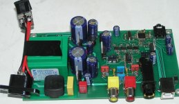
dddac,
You are using the 74HC08 to do the pullup on +D as well as drive the HOST pin, 5->3.3v translation using the LED to drop voltage. Why not simply use 74LV08 or so ?
Also, I had a thought, what about driving those two by using a Zener shunt ? I mean, resistor from USB +V, 3.3v zener on the end, and then drive the +D pullup and HOST with that?
I'm working on a small board so that I can easily generate I2S data, using the PCM2706. Do you know if not connecting VCCL/VCCR will do any damage? I don't think so, since as that part will never be used...
There are many ways leading to Rome 
I just followed this route... The reason using a gate, was to be able to really do the AND function between power of the chip and power on the USB bus. It also allows for some kind of keeping the bus power a way from the chip directly. The 2707 seems to very sensitive and this might help when the USB bus is spiking somewhat. On my DELL notebook I killed once a 2707 by plugging unplugging..
Your suggestions with the zener are 100% valid. Many ways...
Not connection the analog output does not harm the chip. But if it is there, it can be used for a headphone or for comparison. After all this is DIY hobby
Any way, to the other question: The USB-1543 version has the same "soundprint" as the big brothers, The bigger versions however give more low level detail and give more stage.
But still this sound like a very grown up DAC
Also note that in stead of 1.6V output only 0.6 Volt output. This is result of lower voltage ( 6 Volt) to avoid heating or cooling requirement...
Originally posted by dddac
The 2707 seems to very sensitive and this might help when the USB bus is spiking somewhat. On my DELL notebook I killed once a 2707 by plugging unplugging..
Interesting... my own PCM2706 headphone DAC is used all the time... it isn't in a box and i've had my fingers all over it quite a few times with no ESD protection, and it still works! I have 10u right next to the USB socket though, perhaps that helps.
Originally posted by dddac
Your suggestions with the zener are 100% valid. Many ways...
Great, nice low part count, easy to lay out
Originally posted by dddac
Not connection the analog output does not harm the chip. But if it is there, it can be used for a headphone or for comparison. After all this is DIY hobby
Yep, I have a circuit with PCM2706 that uses headphone
If only TI had put the I2S clock pins where the SPI control pins are - would make my job much easier! I'm trying not to use doublesided so I am quite restricted on signal routing.
Thanks!
- Status
- This old topic is closed. If you want to reopen this topic, contact a moderator using the "Report Post" button.
