Howdy.
I am wanting to build a hardware solution for downmixing 5.1 pc audio to 4 channel. So take the 3 plugs and make it 2 plugs. Create a phantom surround and add the subwoofer info. Idealy I'd like to have 2 plugs on one side (L/R and Center/Sub) and one plug on the other, but I'm not sure if the subwoofer needs to be added to all channels, or if just the front is ok.
Anyway, I have some dual channel op-amps around that I have a feeling I'll need, but really dont know how to build the circuit.
I've looked. I've looked a LOT. Can't really find anything, so any help would be appreciated. Thanks!
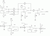
I'm thinking something like this!
subwoofer and center are mixed into the front signal.
The center has a panning pot to adjust the phantom center.
Leave surround unchanged or delay them with some non-inverted opamps.
(The opamps are not specially selected for this purpose.)
The right channel is not drawn.
schematic is just food for thaught !!! not tested !!!!
(supply needs to be symetrical )
Attachments
Thanks a lot seoman! Hopefully I'll get around to testing this out this weekend. If you don't mind, may I a couple questions? Why no power for two of the op-amps, but the rest do? Mainly why power the sub op-amp, but not the center. Also, why is the output of the op-amp wired back into the inverting input (ie: pin 1 to 2)? I've seen that before but never understood why. Anyway, thanks again!
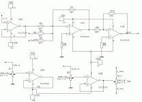
First, I used Dual opamps. So every couple has only supply drawn!
You could decide to use quad opamps, wich lueves you with even less supply signals drwan.
Every opamp needs it's energy!
Every opamp needs a feedback signal (or else it starts behaving extreemly weird, it becomes a comparator.
When connecting out to inv-in an opamp becomes an amplifier with an multiplication of +1.
Wich is perfect for buffering. High input impedance, low output impedance.
There is one major error in the drawing.
U1B needs a feedback resistor! Just like U1A has one.
So a here is a corrected version, with the extra powerlines.
Attachments
- Status
- This old topic is closed. If you want to reopen this topic, contact a moderator using the "Report Post" button.

