Replace with what ?
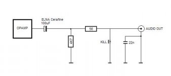
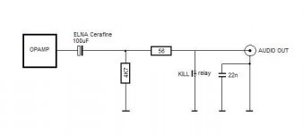
Cap blocks DC (there will be a measurable voltage across it), one resistor is for short circuit protection (mute transistors), the other one is for output impedance/high pass filter.
For auricap try maybe intertechnik in Germany. But that's from the top of my head, so there may well be a better option.
HTH
BTW, if your CDP output schematic is the same as the CD950, then removing the 3 (!) muting transistors also does a lot to the sound.
Replace with what ?
With better capacitor. BlackGate, Auricap... ?
BTW, if your CDP output schematic is the same as the CD950, then removing the 3 (!) muting transistors also does a lot to the sound.
CD960 has no muting transistor. Only relay. See attached schematic...
In the meantime I removed this ELNA Cerafine 100uF/25 V cap and sound improved.
I suppose that sound will improve even further if I replace resistor with
better one (Vishay...?)
Attachments
@lf said:
In the meantime I removed this ELNA Cerafine 100uF/25 V cap and sound improved.
I suppose that sound will improve even further if I replace resistor with
better one (Vishay...?)
Check for DC offset on the rca out and remove the 4k7 resistor too.
hi.
Since all recent opamps are shortcircuit proof, you can remove both caps, replacing the 100uF with a wire. Both resistors can also be removed. As the muting is by relay, leave it in place. You will not gain anything by removing it as you would if the muting was by transistor. [most amps are capacitor coupled so a little DC on the input will do no harm]
Further improvements can be had by removing ALL the headphone amp circuitry [if fitted] and by replacing the opamps.
By far the greatest improvement will be had by replacing the clock with a better one [with it's own power supply]
Andy
lucpes said:
Check for DC offset on the rca out and remove the 4k7 resistor too.
Thank you for your advice.
I have cap at the input of my 41Hz AMP4. I suppose this cap will block DC?
poynton said:
Further improvements can be had by removing ALL the headphone amp circuitry [if fitted] and by replacing the opamps.
Andy
I removed headphone amp month ago and replaced opamps with AD825 at the same time.
poynton said:hi.
By far the greatest improvement will be had by replacing the clock with a better one [with it's own power supply]
Andy
Yes. I already replaced clock with LCAudio clock with separate power supply.
Thank you for your advice.
I just saw the CD960 uses a TDA1541
If so, maybe try to feed it the low jitter clock directly (2.8 Mhz!) The benefit of your clock upgrade will be even better.
Also, you can replace the rectifier diodes with better ones. Cap upgrades for the power pins of selected IC's is also a good idea.
happy modding
I originally thought it was very similar to a 950, but then again... my mistake
poynton said:
Both resistors can also be removed.
Andy
I would leave the smaller value series one, it is there to isolate the opamp from any parallel capacitance down the chain (cable, input on next amp). It is standard practice and does not have any real influence in sound.
Alien8
I replaced TDA1541A at first with TDA1541A S1 (single crown)
and than with TDA1541A S2 (double crown). Still I'm not sure which one sounds better... Can you explain in detail (maybe shematic or picture) how to feed tda with the clock directly as you mentioned. I already replaced xtall with LClock... Or if you can point where to search for the info... [/QUOTE]
I already replaced diodes with shotky. But still there are two more sets of diodes waiting for replacement.
Caps are ELNA Cerafine and I doubled capacity with the same Cerafine caps (100uF/25V).
Also added 50.000uF caps after rectifier section.
Result of that mod was huge improvement.
Thank you for your help and info.
Post #7
I just saw the CD960 uses a TDA1541
I replaced TDA1541A at first with TDA1541A S1 (single crown)
and than with TDA1541A S2 (double crown). Still I'm not sure which one sounds better... Can you explain in detail (maybe shematic or picture) how to feed tda with the clock directly as you mentioned. I already replaced xtall with LClock... Or if you can point where to search for the info... [/QUOTE]
Also, you can replace the rectifier diodes with better ones. Cap upgrades for the power pins of selected IC's is also a good idea.
I already replaced diodes with shotky. But still there are two more sets of diodes waiting for replacement.
Cap upgrades for the power pins of selected IC's is also a good idea.
Caps are ELNA Cerafine and I doubled capacity with the same Cerafine caps (100uF/25V).
Also added 50.000uF caps after rectifier section.
Result of that mod was huge improvement.
Thank you for your help and info.
I would leave the smaller value series one, it is there to isolate the opamp from any parallel capacitance down the chain (cable, input on next amp). It is standard practice and does not have any real influence in sound.
lucpes
Thank for the advice. What kind of high quality/low noise resistor do you reccomend in this place?
It depends on your clock frequency. I my case I only had to divide it by two (1/2 74HC74) and feed it to my dac (which is a 1547).
It would be interesting to know more about the clock distribution in your player (I can 't find the related info on the net and I don't have a manual)
Anyway, regardless of the clock scheme used, the only place where it counts is at the dac. You can still feed the undivided clock to the servo chips and where else it is required. That way the whole thing is still synchronous.
Also if you replace or upgrade caps, it may be interesting to check for keramic smd caps in parallel (not always close enough to the power pins). I tend to completely remove them or change them with wima MKP's directly at the pins (where it's supposed to be)
I'm pretty sure the double crown is not really suited in your application. Don't understand me wrong, but a lot is lost by the opamp filter section... I would think it's a shame, there are better ways for a double. (wish I had some...)
You can find tons of information in this forum.
HTH
Alien
- Status
- This old topic is closed. If you want to reopen this topic, contact a moderator using the "Report Post" button.
- Home
- Source & Line
- Digital Source
- Suggestions for CD960 audio out cap replacement