Hello all,
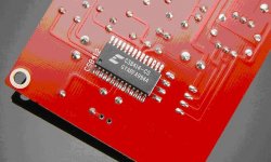
I made a Cardinal Sin in DIY a few days back....I was soldering my new TDA1543 - CS8414 DAC up while EXTREMELY TIRED. I finally went to sleep and in the morning I noticed many of my solder joints were less than Ideal. The tiny solder joints that attached the CS8414 were extremely difficult (while tired) and after a little clean up, they seem fine. After checking for continuity on some of the pins and all of the tracings, I fired her up. I connected the optical out of my Panasonic DVD player to the optical input to the DAC... The DAC can be seen here...
http://us.hifidiy.net/Article.asp?ArticleId=152
I also correctly jumpered the digital input to the Optical In and not Coax In.
Now from what I gather, the CS8414 on this board is connected in such a way that the optical output of my Panny should work - in other words, no Sony/Philips/I2S format issues here...
Anyway, no sound. nothing. Power supply is a 12VDC 1.2A power supply I was using for my Tripath SI. - Unloaded it was 12.3VDC. Center Positive.
I checked the voltage at the TDA1543 pin 5 (VDD) and got 5V, which is exactly what the first LM317 should be providing. I also checked the voltage at both Pin 22 (VA+) and pin 7 (VD+) and they also were 5VDC which are what the other LM317 Voltage regulator is providing, so theres power to both chips..should be good to go here.
There are 8 polyester MKT .1uF caps that I assumed were non-polar, and two Nichicon Muse BP 10uF caps that I again assumed was non-polar, and two 2200pF Polystyrene caps that also were assumed non polar, as they did not indicate any polarity. All other caps were installed correctly.
Without audio input and the 12V power supply connected (LED powers up fine), I measured analog output left/right pins on the TDA 1543 - pin 8 (AOR) and 10 (AOL) and they both read a steady 3VDC referenced to power ground. Pin 7 (Vref) read 2.18VDC referenced to ground.
Anyway, is there any other way I can see if I fried the CS8414 or TDA1545 by checking some of the other pinouts? I have No sound at all - no hum or hiss...I also checked the Coax input with the digital out of my PC Sound Card (Sound Blaster Live) - nothing...
Any help here is appreciated. I will no longer do any soldering (or any electrical work for that matter) when exhausted.
Mine worked on the first try (I must have good luck, my kookaburra and amp6 worked the first time also).
I don't think this is your problem, but make sure your outputs on dvd or pc are set to pcm. You would get a bad/weird sound though if was set wrong (at least I did the first time i fired it up- then realized I needed to set output to pcm).
I have 6 capacitors that are polarized (all the ones that are round on the silkscreen).
Take a magnifier and look over all solder connections.
I think most chips are pretty tolerant of mistakes, except when power goes where it can't be tolerated.
I don't know what you have for test equipment, I don't have an oscilloscope, but do have a logic probe (kinda the wrong tool for audio). With my logic probe, I would see if I could see some activity along the digital path. At least then you could determine if problem is before or after tda1543. Or maybe use a cheap little speaker/headphone with a cap in series to 'probe' for 'sounds'.
Maybe if get a little time, I can see what mine measures at various points.
It is possible that you may have soldered CS8414 upside down and since the power supply pins are at the middle it would not cause a short circuit.Just that the inputs and outputs are in the wrong place.Is the notch facing the right direction?; or white dot at pin 1 position?
john65b said:
I connected the optical out of my Panasonic DVD player to the optical input to the DAC...
Check to see if the CS8414 is locking to the signal from the DVD player. Pins 25 and 28 on the CS8414 are both low (0V) when the CS8414 has locked.
Correction - I have 5V on Pins 25/28 when Digital input is not connected, and zero when it is...so we are good here. My previous post was on another set of pins...
I noticed that there are only three pinouts that go to the TDA1543...pins 11, 12, and 26...I was reading the pin voltages on pins 26, 11 and 12 when I noticed I had two different voltages on pinout 12 on the CS8414 chip leg and on the pad...so I looked closer at the solder blob with a jewlers loupe and notied it was not totally connected. So i reconnected them and violla, now it works perfectly. I had thought bad soldering had fried one of the two chips...
I had totally given up on this as it has taken the better part of three days to troubleshoot. At one point I flung the board across the room.
Well, now on to part three, setting the board in a nice case with a stepped attenuator for a DAC/passive Preamp...
Thanks everyone for your help.
john65b said:At one point I flung the board across the room.
Regardless of the problm, that's the first thing you should have done. I think everyone here just assumed this was already done. Its a universal troubleshooting technique that works on everything. And if you can't fling it, hit it.
So yes, I got it working...but after seeing a few of the Entech Number Crunchers 203.5 on ebay for $35 each, wonder how the CS8414/TDA1543 16 bit setup would compare to the Entech CS8412/CS4329 20 bit combo...
Both options are very late 1990's (CS8414 is relatively new)
Any opinions here???
Both options are very late 1990's (CS8414 is relatively new)
Any opinions here???
senderj said:I may be wrong, but I thought all DAC need a clock. I didn't find any crystal in the photo of this min DAC. Where is the clocking pulse that drive the 8414 and 1543 from?
8414 recovers it from the input data. If you read the datasheet it allows both modes of operation.
- Status
- This old topic is closed. If you want to reopen this topic, contact a moderator using the "Report Post" button.
- Home
- Source & Line
- Digital Source
- TDA1543/CS8414 Problems...