
That was bad when I tried to reduce it to meat the specifications of 1000X1000 the pixels got messed up. Here is the photo :
An externally hosted image should be here but it was not working when we last tested it.
VCOM?
... looks like some kind of capacitance interface control is possible here >> into VCOM ... touch a pad @ C1 / C3 and change in capacitance might trigger a signal ... ??
The spec sheet should indicate such possibilities ... or not ...
Further: you knew of course that the 5.0 VDC from the USB connector can power this whole circuit = 5 VDC and up to 400 mAmps., although an upper limit of 100 mAmps should be used for "quality" audio work. (Here is a 12 VDC powered USB hub with some decent filtration /regulation: http://3dotaudio.com/3DotAudioKits/index.html ... inc. isolation from the +5 VDC of host computer = pin#1 disconnected from host.)
....
(Mercinary announcement: that's my web site above.)
I am on business trip, but will see if I can find some time answering your emails this evening when I am back home.
A general statement I can make any way for the forum. The PCM2707 is a sensitive cmos chip and can be damaged by for example putting wrong polarity at the chip and voltage spikes which can be induced by the PC/USB interface it self. With my old Dell Notebook I had a defect once when switching on/off. All my other PC's and Notebooks have no problem. But it just stays DIY and things can break down pretty easy sometimes, even without realy knowing what was done wrong or what hapened.
This is my general comment, but I will come back to your specific case by direct email
doede
static sensitive?
" ... The PCM2707 is a sensitive cmos chip and can be damaged by for example putting wrong polarity at the chip and voltage spikes which can be induced by the PC/USB interface it self. ..."
This can usually be resolved by using Schottky diodes clamping the inputs to the power rails ... but of course that may change the input impedence some what ...
Have you checked the 74HC08 to make sure that it is still good? And is it really absolutely necessary?
Most application circuits lack some real world niceties like effective esd protection and emi compliance. I would recommend a quad winding common mode choke on the usb buss right at the connector - this will strip a lot of common mode rubbish off of the usb and also provides some needed esd protection. Low voltage transorbs will provide additional protection and are also effective against lower frequency glitches and transients on the buss.
Logic gate inputs should never be directly connected to the outside world - use a small rc (1K/1000pF) at each input to provide esd protection.
I thought the USB host line operates at 5V, if so you should level shift the inputs to the '08. I haven't checked the usb spec lately so I might be wrong.
Tie unused inputs on the '08 to either ground or 3.3V through a resistor.
First, you probably damaged it with electrostatic discharge (ESD). You should always be grounded when dealing with an exposed circuit board assembly or loose parts.
Second, the USB interface should prefereably have 27 ohm resistors in series with 47 pF caps to ground at the input pins. Otherwise, the longest USB cable, 5 meters will probably not work.
Steve N.
Empirical Audio
Second, the USB interface should prefereably have 27 ohm resistors in series with 47 pF caps to ground at the input pins. Otherwise, the longest USB cable, 5 meters will probably not work.
Steve N.
Empirical Audio
correct ...
" ... Second, the USB interface should prefereably have 27 ohm resistors in series with 47 pF caps to ground at the input pins. Otherwise, the longest USB cable, 5 meters will probably not work. ..."
Yes. Trying to match the dynamic impedence of the USB host / hub ports is a bear on the receiving end. And for audio work especially, ignoring the 5 meter (16 foot) cable length requirements will limit usefulness considerably.
(I still don't quite understand why you want to limit your project to 16 bits ... ? have you considered http://focus.ti.com/docs/prod/folders/print/pcm1704.html ?? ... no offence)
Guys,
I'm building the same - a self powered PCM2707 DAC & am learning from this thread. My questions are not to hijack this thread or to divert from excetara2 problem but to understand it better & maybe shed some light.
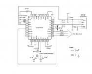
I have built the schematic as per the datasheet but without the connections for the analog out. I haven't got it working yet.
I have a fully built & working AW-D3 board using the PCM2707 chip which I will carefully perform some measurements on.
Audioengr, - so if I understand correctly the 22ohm R on the D+ & D- input should be 27ohm with 47pf cap to ground?
excetara2, - what is the purpose of the 08 chip?
John
I'm building the same - a self powered PCM2707 DAC & am learning from this thread. My questions are not to hijack this thread or to divert from excetara2 problem but to understand it better & maybe shed some light.
I have built the schematic as per the datasheet but without the connections for the analog out. I haven't got it working yet.
I have a fully built & working AW-D3 board using the PCM2707 chip which I will carefully perform some measurements on.
Audioengr, - so if I understand correctly the 22ohm R on the D+ & D- input should be 27ohm with 47pf cap to ground?
excetara2, - what is the purpose of the 08 chip?
John
Attachments
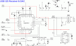
AW-D3 schematic - nearly identical to excetara2 schematic of DDDAC board
http://www.audioworkshop.com.hk/download/AW_D3.pdf
http://www.audioworkshop.com.hk/download/AW_D3.pdf
jkeny said:
Audioengr, - so if I understand correctly the 22ohm R on the D+ & D- input should be 27ohm with 47pf cap to ground?
John
Yes, the 47 pF are on the chip input pins.
Steve N.
Empirical Audio
I just got my board working - when I say my board it is really just an adaptor board for TQFP chips running off a 3.3V supply (a regulator board rescued from a PC) - to which I attached a low jitter 12MHz oscillator running off separate 3.3V supply (another PC board) - linked to the TDA1543 DAC half of the AW-D3 board. It sounds crystal clear & excellent - can't say that it is any better than the AW-D3 board though with the same supplies.
One thing surprised me - it worked. I wasn't expecting it to work as I had tried to power it up a number of times in the past when it was incorrectly wired & it wasn't recognised by the PC - so I thought I had blown the chip but apparently not - seems more robust than my past experiences would suggest or maybe i was just lucky.
Pretty much the same schematic as excetara2 but all analogue out pins are not used & R15 is a cap not an R - also no gate on pull up of D+ so no 74HC08 - hope this remains working.
Anyway, always on to the next mod - active output stage using OPA660 I/V & change of DAC to TAD1387.
So good news for a change - not a blown chip
- Status
- This old topic is closed. If you want to reopen this topic, contact a moderator using the "Report Post" button.
- Home
- Source & Line
- Digital Source
- USB controller problems on DAC?