Been trying to add a separate tranny to my CD723/CD4000 without success. Followed the modding guide found on www.ptsoundlab.com. Its in French but the link below will give you an English translation via google.
http://translate.google.com/transla...&hl=en&ie=UTF-8&oe=UTF-8&prev=/language_tools
Did what the guide stated. I cut the 10-0-10V (White- Green-White) winding of the original & replaced it with separate 9-0-9V tranny. Player works fine but the display won't light up? What am I doing wrong?
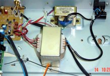
I stumbled upon this pic on the internet of similar installation that apparently works. Similar setup & connections but with an additional wire coming out from the 9-0-9V. I'm not completely sure what this additional wire is connected to from the pic.
Is the separate tranny being reference to the 0V of the original tranny? Taking stab in the dark, it appears that the additonal wire is connecting the one 9v of the new tranny to the 0v of the original. I could be wrong ... so I hope someone in the know can clue me in?
http://translate.google.com/transla...&hl=en&ie=UTF-8&oe=UTF-8&prev=/language_tools
Did what the guide stated. I cut the 10-0-10V (White- Green-White) winding of the original & replaced it with separate 9-0-9V tranny. Player works fine but the display won't light up? What am I doing wrong?
I stumbled upon this pic on the internet of similar installation that apparently works. Similar setup & connections but with an additional wire coming out from the 9-0-9V. I'm not completely sure what this additional wire is connected to from the pic.
Is the separate tranny being reference to the 0V of the original tranny? Taking stab in the dark, it appears that the additonal wire is connecting the one 9v of the new tranny to the 0v of the original. I could be wrong ... so I hope someone in the know can clue me in?
Attachments
poynton:
Thanks. I do have the manual but I'm still confused on the connections acually ... no electronics background you see. I've learnt by "Modding-by-Numbers"
When you say reconnect the 0v green wire ... what do you mean?
1) Reconnect the 0v .... meaning there are 2 x 0v connections on the pcb? One from the new tanny & one from the orginal?
or
2) New 9-0-9v connects to the pcb and original green (0v) wire connects to one of the 9v tabs on the new tranny. This what the posted pic suggest but wasn't too sure whether this is correct?
How did you add your tranny?
When you say reconnect the 0v green wire ... what do you mean?
1) Reconnect the 0v .... meaning there are 2 x 0v connections on the pcb? One from the new tanny & one from the orginal?
The green is the ground for the 27v winding. (and possibly for the 5vac winding). These are required for the display.
If you look carefully at the photo, I think the 'extra' red is connected to the green wire behind the transformer. I do not think this is quite correct although it appears to work!
The translated 'French Article' does seem to say 'keep the green'.
Andy

- Status
- This old topic is closed. If you want to reopen this topic, contact a moderator using the "Report Post" button.
- Home
- Source & Line
- Digital Source
- Help! Adding separate tranny in CD723/CD4000