I am trying to interface an S/PDIF circuit based on a Crystal CS8405 S/PDIF transmitter chip with a RioReceiver network MP3 player. However, when I tap into the I2S signals feeding the DAC on the board, I get severely distorted sound from the S/PDIF output of the Crystal circuit. One channel is distortion-free until the signal reaches a certain volume, while the other channel is severely distorted. If I reset the chip, sometimes the severely distorted channel switches. I get essentially the same results regardless of the format (right justified, left justified, I2S) chosen. I have successfully used the circuit in other applications without problems. I have also tried both buffering and straight through connections. I'm convinced all the connections are correct after triple checking them. Do I need to invert one of the signals? Which one(s)? Any ideas?
Here is link to an MP3 sample of the output.
http://www.eutronix.com/media/Garbled.mp3
Thanks,
Stu
Here is link to an MP3 sample of the output.
http://www.eutronix.com/media/Garbled.mp3
Thanks,
Stu
Thanks.
I do know about the various formats of I2S, however, I believe the Crystal CS8405 supports them all. The signals I am tapping into go to a BB PCM1716 DAC, so it has to be one of the formats it supports. The Crystal chip supports all of them. Anyone else have ideas?
Stu
I do know about the various formats of I2S, however, I believe the Crystal CS8405 supports them all. The signals I am tapping into go to a BB PCM1716 DAC, so it has to be one of the formats it supports. The Crystal chip supports all of them. Anyone else have ideas?
Stu
Yes, by "tap into" I mean soldering wires to the pads where the signals are, well actually, it's a duplicate set of pads for an alternate DAC. That method works fine on another device I use it on. I also have everything buffered as mentioned earlier. What other alternatives are there to "grabbing" the I2S signal from an existing device, other than attaching wires?
Stu
Stu
The CS8405A will accept data in three formats only one of which complies with I2S standard as specified by Philips, the other two being Left and Right justified data. The PCM1716 also accepts data in three formats and as with the CS8405A each format covers 16-24 bit data.If, assuming the CS8405A is set to receive I2S data, the PCM1716 is receiving data in a format other than I2S, chaos will reign downstream of CS8405A. The LRCLK will be inverted and the sign bit and the MSB will be out of position at the very least. I would suggest you check the mode pins on the PCM1716 and confirm the chosen format if the PCM1716 is in hardware mode. If it is in software mode it is a case of trial and error.
ray
ray
Thank you for your suggestions.
I have tried all the format modes of the CS8405, using jumpers on a test board I built. Right justified doesn't seem to work at all. Left justifed and I2S work about the same (terribly as is demonstated in the link in my first post). As far as I know, the PCM1716 is operating in software mode (device uses its digital volume control). I am trying to find out from one of the engineers of the product I am interfacing with, what format is being sent to the PCM1716, but so far no luck. Besides, the Crystal chip doesn't seem to like the signal no matter what format it is set for. It seems odd to be that my circuit would work so well in one device and so poorly in another.
Frustrating!
Stu
By working DAC, I assume you mean the one downstream of the S/PDIF signal coming from the CS8405? That would consist of a Midiman Flying Cow with Monster Cable coaxial digital interconnect. Not exactly audiophile grade, but works for testing.
The master clock is coming from a 11.2896 mHz clock derived via PLL from a 20 mHz clock. This clock and the other I2S signals are split off on the device circuit board to two sets of pads located about .25" apart, one for the PCM1716 and one for a Crystal CS4341 (unpopulated alternate DAC). I soldered a conductor from a six inch piece of 3M rainbow ribbon cable to each of the corresponding I2S pads on the CS4341 pads and routed them to my CS8405 circuit. The audio going to the PCM1716 is 44.1 kHz and the CS8405 is set to 256fs.
Should work, I don't get it!
Stu
Identifying the Format
Several thoughts come to mind here:
First off, as a matter of semantics, I2S (IIS) is a Philips defined protocol with the following features:
The word clock (LRCLK) is low for left channel data.
Data is Left MSB justified with the MSB delayed one count after the LRCLK transition (this makes synchronization with arbitrary frame lengths easier to implement).
The data frame length can be arbitrary, but it is typically 32bits and sometimes 16bits.
Technically, all of the other three wire formats aren't I2S.
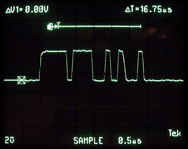
You didn't mention if you are able to look at the signals with a 'scope. I think that you're at a point that this will be necessary, since trial and error configuration hasn't worked.
Because you were getting sound from just one channel, this suggests to me either a problem with the frame length or the word clock.
At first I suspected that the RIO device had a 16bit frame and that the CS8405 needed a 32bit frame (many devices have a fixed 32bit frame). This would result in the left channel data being received (almost) properly with the right channel data also being received by the left channel as super low LSBs.
I took a quick glance at the CS8405 data sheet and saw that it appears to support arbitrary word length, so the above probably isn't your problem.
There are other data formats, sometimes called TDM or DSP formats, that are characterized by a short word clock pulse at the begining of the left (or front left) data. This pulse marks the begining of a sequence for all of the data. The right channel data is expected to begin a certain number of counts later, without a transition of the word clock to specifically mark it.
I think there's a good possibility that this may be what you're running into. It could explain all of the symptoms you've described:
The word clock marker pulse deasserts after a couple MSBs of the left channel data have passed. In some modes, the CS8405 would interpret this deassertion as the beginning of a channel. As long as the music data for that channel was below the level being 'clipped' off by the markerpulse, it will come through. The second channel won't have anything to trigger it.
A scope could quickly prove or disprove this theory. If the word clock has a 50% duty cycle, the theory is wrong. If the word clock is a short pulse, then the Rio device is using some sort of TDM mode, which the CS8405 won't support. Offhand I'm not aware of any other transmitter that supports TDM. The best way to deal with this would probably be to use an EPLD to make some format conversion glue logic.
A scope is useful for identifying data formats. Right justified vs. left justified is immediately apparent. I2S can be distinquished from other left justfied formats by the one bit delay.
Hope that helps.
Brian.
Several thoughts come to mind here:
First off, as a matter of semantics, I2S (IIS) is a Philips defined protocol with the following features:
The word clock (LRCLK) is low for left channel data.
Data is Left MSB justified with the MSB delayed one count after the LRCLK transition (this makes synchronization with arbitrary frame lengths easier to implement).
The data frame length can be arbitrary, but it is typically 32bits and sometimes 16bits.
Technically, all of the other three wire formats aren't I2S.
You didn't mention if you are able to look at the signals with a 'scope. I think that you're at a point that this will be necessary, since trial and error configuration hasn't worked.
Because you were getting sound from just one channel, this suggests to me either a problem with the frame length or the word clock.
At first I suspected that the RIO device had a 16bit frame and that the CS8405 needed a 32bit frame (many devices have a fixed 32bit frame). This would result in the left channel data being received (almost) properly with the right channel data also being received by the left channel as super low LSBs.
I took a quick glance at the CS8405 data sheet and saw that it appears to support arbitrary word length, so the above probably isn't your problem.
There are other data formats, sometimes called TDM or DSP formats, that are characterized by a short word clock pulse at the begining of the left (or front left) data. This pulse marks the begining of a sequence for all of the data. The right channel data is expected to begin a certain number of counts later, without a transition of the word clock to specifically mark it.
I think there's a good possibility that this may be what you're running into. It could explain all of the symptoms you've described:
The word clock marker pulse deasserts after a couple MSBs of the left channel data have passed. In some modes, the CS8405 would interpret this deassertion as the beginning of a channel. As long as the music data for that channel was below the level being 'clipped' off by the markerpulse, it will come through. The second channel won't have anything to trigger it.
A scope could quickly prove or disprove this theory. If the word clock has a 50% duty cycle, the theory is wrong. If the word clock is a short pulse, then the Rio device is using some sort of TDM mode, which the CS8405 won't support. Offhand I'm not aware of any other transmitter that supports TDM. The best way to deal with this would probably be to use an EPLD to make some format conversion glue logic.
A scope is useful for identifying data formats. Right justified vs. left justified is immediately apparent. I2S can be distinquished from other left justfied formats by the one bit delay.
Hope that helps.
Brian.
Thanks Brian for all your insight.
I have not tried a scope yet. I will tonight. Is it possible that the PCM1716 (built in DAC) could work on one of the two aforementioned formats, but not the CS8405? They both seem to support the same formats.
I'll post the results from the scope tonight or tomorrow.
Stu
I have not tried a scope yet. I will tonight. Is it possible that the PCM1716 (built in DAC) could work on one of the two aforementioned formats, but not the CS8405? They both seem to support the same formats.
I'll post the results from the scope tonight or tomorrow.
Stu
I need to pay closer attention.
I missed the point that you had identified the Rio's DAC as a PCM1716. (It's obvious when I re-read the thread).
I looked at the PCM1716 data sheet. It doesn't support any TDM type of formats. So much for that theory...
It still would be useful to try scoping the signals. Let's see what they look like.
Another thought:
Are you sure that the PCM1716 is in software mode? There might be a small chance that the device feeding it is controlling the volume instead. To be sure, look at the MODE pin (p24). If p24 is high, then the PCM1716 is being configured by software. If it's low, then you can look at the other configuration pins. (I know this is a long shot, but I thought I'd ask just in case.)
Could you identify the device generating the signals? It might reveal some more clues.
Brian.
maczrool said:Is it possible that the PCM1716 (built in DAC) could work on one of the two aforementioned formats, but not the CS8405?
I missed the point that you had identified the Rio's DAC as a PCM1716. (It's obvious when I re-read the thread).
I looked at the PCM1716 data sheet. It doesn't support any TDM type of formats. So much for that theory...
It still would be useful to try scoping the signals. Let's see what they look like.
Another thought:
Are you sure that the PCM1716 is in software mode? There might be a small chance that the device feeding it is controlling the volume instead. To be sure, look at the MODE pin (p24). If p24 is high, then the PCM1716 is being configured by software. If it's low, then you can look at the other configuration pins. (I know this is a long shot, but I thought I'd ask just in case.)
Could you identify the device generating the signals? It might reveal some more clues.
Brian.
Thanks again Brian, you were right about the mode. It's hardware! Pin 24 is low. Format pins 28 and 23 are high, indicating 24 bit I2S format. Odd thing about the volume control, was that although apparently not handled by the DAC, changing the did not lower the volume through the CS8405.
Scope results to come.
The device is a Sonic Blue RioReceiver network MP3 player. It's discontinued, so I can't point you to a website. I believe it uses ~75 mHz ARM processor for decoding.
Stu
Scope results to come.
The device is a Sonic Blue RioReceiver network MP3 player. It's discontinued, so I can't point you to a website. I believe it uses ~75 mHz ARM processor for decoding.
Stu


rfbrw said:Does the PLL drive the source of the I2S signals driving the PCM1716 and when you say the masterclock is derived from a 20Mhz source what is used as a reference ?
According to one of the engineers of the device:
"The MCLK is 11.2896MHz. Everything on the board is generated from one xtal [20.0000 MHz] and the Cypress CY2292 chip which has programmable (at production, anyway) dividers/PLLs/etc"
- Status
- This old topic is closed. If you want to reopen this topic, contact a moderator using the "Report Post" button.
- Home
- Source & Line
- Digital Source
- I2S Problems