Hi all
At the risk of starting a war...
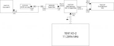
here is a simplified clock scheme as used in my CDP (philips) attached
it already has an upgraded clock TENT XO-2 at 11.2896 MHz.
This clock is injected at SAA7350
The clean clock is then distributed *through* a number of chips, which I'm sure will annihilate most of the benefits from the upgrade.
That is why I believed that the upgrade from the original clock to the TENT XO was somewhat of an improvement, but not spectacular.
So I'm considering to change it too... (see next post)
At the risk of starting a war...
here is a simplified clock scheme as used in my CDP (philips) attached
it already has an upgraded clock TENT XO-2 at 11.2896 MHz.
This clock is injected at SAA7350
The clean clock is then distributed *through* a number of chips, which I'm sure will annihilate most of the benefits from the upgrade.
That is why I believed that the upgrade from the original clock to the TENT XO was somewhat of an improvement, but not spectacular.
So I'm considering to change it too... (see next post)
Attachments
part 2 fanouts
see again attached image
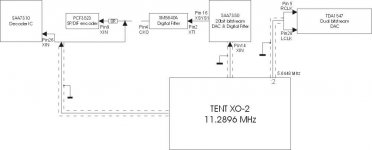
This would mean that the most important chips get the clean stable clock, in the distant future I plan to make this a machine a transport and tap I²S out from the SAA7310 directly, which is why I also want to feed the clock there.
There are a couple of problems though...
1. Can the TENT XO cope with so many outputs ? I'm sure some buffer might be needed, but it would be nicer if it could be omitted.
2. A divide by 2 output can be added to the TENT XO, as mentioned in other posts on this forum. I will try and get hold of Guido Tent for this.
3. I've seen in the datasheets that there is some 90 degrees phase shift between the XIn and XSYS1 in the SAA7350. I don't know if that matters, or if it's necessary. It will surely change the timing between the chips, so the logical question : is that sort of shift necessary ?
4. Something different : what about groundloops between the TENT XO and the main board ? The clocklines have to be shielded, but should or should it not be at both ends ?
Any thoughts ? Guido T, if you're reading this ??
TIA
see again attached image
This would mean that the most important chips get the clean stable clock, in the distant future I plan to make this a machine a transport and tap I²S out from the SAA7310 directly, which is why I also want to feed the clock there.
There are a couple of problems though...
1. Can the TENT XO cope with so many outputs ? I'm sure some buffer might be needed, but it would be nicer if it could be omitted.
2. A divide by 2 output can be added to the TENT XO, as mentioned in other posts on this forum. I will try and get hold of Guido Tent for this.
3. I've seen in the datasheets that there is some 90 degrees phase shift between the XIn and XSYS1 in the SAA7350. I don't know if that matters, or if it's necessary. It will surely change the timing between the chips, so the logical question : is that sort of shift necessary ?
4. Something different : what about groundloops between the TENT XO and the main board ? The clocklines have to be shielded, but should or should it not be at both ends ?
Any thoughts ? Guido T, if you're reading this ??
TIA
Attachments
Re: part 2 fanouts
Hi
The XO can typically drive 3 CMOS gates, so in your suggested diagram, tehre are no problems.
Coax screen needs to be connected at both ends. the module only connects to +, ground is connected by means of the coax screen, and filtering at the XO2 board ensures that only DC runs there.
best
Alien8 said:see again attached image
This would mean that the most important chips get the clean stable clock, in the distant future I plan to make this a machine a transport and tap I²S out from the SAA7310 directly, which is why I also want to feed the clock there.
There are a couple of problems though...
1. Can the TENT XO cope with so many outputs ? I'm sure some buffer might be needed, but it would be nicer if it could be omitted.
2. A divide by 2 output can be added to the TENT XO, as mentioned in other posts on this forum. I will try and get hold of Guido Tent for this.
3. I've seen in the datasheets that there is some 90 degrees phase shift between the XIn and XSYS1 in the SAA7350. I don't know if that matters, or if it's necessary. It will surely change the timing between the chips, so the logical question : is that sort of shift necessary ?
4. Something different : what about groundloops between the TENT XO and the main board ? The clocklines have to be shielded, but should or should it not be at both ends ?
Any thoughts ? Guido T, if you're reading this ??
TIA
Hi
The XO can typically drive 3 CMOS gates, so in your suggested diagram, tehre are no problems.
Coax screen needs to be connected at both ends. the module only connects to +, ground is connected by means of the coax screen, and filtering at the XO2 board ensures that only DC runs there.
best
Thanks for you reply. You have mail BTW...
Will this not create ground loops when all screens are connected to both the CD player ground and the XO module ground ?
Unfortunately the module will then be loaded by 3 gates already, without the divide by two FF. (the clock connection to the SAA7310 is also connected to the PCF3523).
What about timing problems ?
Alien8 said:Thanks for you reply. You have mail BTW...
Will this not create ground loops when all screens are connected to both the CD player ground and the XO module ground ?
Unfortunately the module will then be loaded by 3 gates already, without the divide by two FF. (the clock connection to the SAA7310 is also connected to the PCF3523).
What about timing problems ?
Hi
Th induced voltage due to the groundloop is equal in screen and signal wire, hence the differential voltage is zero.
The PCF3523 has an internal buffer + output, that could be used to drive the 10
best
Mods are done ! Thanks to Guido Tent
Hi All
Just in case anybody 's interested (which I pretty much doubt), I have completed the clock upgrade as planned.
I could not have done this without the kind help from Guido Tent !! He showed me how to add the clock divider to his XO and patiently answered all my questions.
So now all the 'important' chips (for me at least) get the stable clock, including the 128Fs to the TDA1547 dac.
Once again there is a definite improvement, though it is subtle.
This about concludes the mods I can do to this player, a Philips CD950 by the way. As mentioned elsewhere, it has a CDM9 transport and the TDA1547 dac. The latter supposebly the best of the TDA15* series, at least on paper. I'm convinced that the implementation needs to be very carefull. As I understand there is no alternative then adding a digital filter/oversampler to get it to work, which chips can be seen above ! So maybe that is not the best way to use it.
A short overview of all mods done to this player :
Addition of Tent XO-2 (some but not spectacular improvement)
Removal of muting transistors and shunt ceramic output caps (big improvement)
Swapping of output opamps to AD826, others were tested as well, but this proved to be the best here. At the same time some BG caps replaced some critical ones around the analog audio part. (again big improvement)
Elimination of the on chip I/V opamps on the TDA1547, now I/V is done with a modified AD844 scheme (credits go to Pedja Rogic), followed by a discrete differential amp with class A output follower (credits go to UltrAnalog) (again an improvement in detail could be heard, especially in extreme lows and highs)
The 'old' analog stage is now completely bypassed by this. So now there is only a 1st order lowpass filter, less than 15 degrees phase shift at 20kHz
Modifications as given in this thread to improve the clock distribution (even more detail can be heard, though that is subjective)
That's about it for now, I may very well continue to mod it in the future.
Anyway thanks to Guido Tent, Pedja, UltAnalog, Klaus Witte for their contributions.
Greetz
- Status
- This old topic is closed. If you want to reopen this topic, contact a moderator using the "Report Post" button.