The PLL doesn't lock in the Tentlabs DAC (Tube DAC). I changed already U11, U12, U13, U14, U15, U17 without result. I checked the resistors and capacitors of the PLL circuit. The bicolor LED lights red at the start and lights than alternate green or red.
The output voltage at pin 6 of the TLC251 is a unstable voltage around about 2.5 V. I use the Tentlabs VCXO.
Please help.
The output voltage at pin 6 of the TLC251 is a unstable voltage around about 2.5 V. I use the Tentlabs VCXO.
Please help.
Attachments
jpfastre,
Before changing parts did You try the Dac with different sources?
This Dac is really sensitive for the right [absolute] frequency value of the CD drive unit's clock source. It's not enough to suppose that Your drive is good / expensive so it's OK. For example I have a Rotel RCD 990 which was totally off, I had to adjust it. On the other hand some CD roms were just right [with their ceramic resonator..]
I would say it's a defect of the PLL if You were not able to find not even one drive unit with which it would work.
Ciao, George
Ps.: By the way it's a TLC271 which was originally designed in..
Not a big difference, but maybe some offset problems could come up without adjustment?
Have you asked Guido Tent? I bet he will be happy to help you out.
I'll try it .
Thanks
Before changing parts did You try the Dac with different sources?
I tried it with two CD players and one DCC recorder with the same result.
Ps.: By the way it's a TLC271 which was originally designed in..
My mistake, it was a TLC271
Any suggestions?
Next idea: are You sure that the Cs8412 itself gets locked right in the first place?
Because from Your description it seems that the dc levels / circuit behaviour is OK for a free running system.. So, does things change when You plug/unplug the input SPDIF signal?
Though it will be hard to do smthing without at least a scope..
Ciao, George
Because from Your description it seems that the dc levels / circuit behaviour is OK for a free running system.. So, does things change when You plug/unplug the input SPDIF signal?
Though it will be hard to do smthing without at least a scope..
Ciao, George
Next idea: are You sure that the Cs8412 itself gets locked right
Hallo George
When I remove signal:
The LED lights yellow= signals no SPDIF
pin 25 of CS8412 goes high = ERF
pin 6 of TLC271 goes to zero Volts
I have a simple old one channel scope.
What can I do?
Regards
JP:
Jp,
So it seems to work, the 8412. And also the phase comparator section works in some way. Hm.
With the scope You should observe signals similar to these:
http://www.diyaudio.com/forums/showthread.php?postid=175521#post175521
see also here:
http://www.diyaudio.com/forums/showthread.php?postid=185296#post185296
If You checked:
all power supplies, with the scope, and it's 5V DC with absolutely no signs of oscillation, also it's 6V Dc on the TLC271, and no osc. also there, [Always suspect those LM317's.. aproposito, what kind of cap did you apply on the reg's output? 10uF solid polimer - might be a problem]
And there they are both the ~ 700 KHz 5v square wave signals on the output of the two counters/dividers;
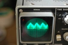
and there it is the sawtooth signal as described in above link on the "pll sound" output;
Then still there is the possibility that your external sources are so unfortunate [or the VCXO is not up to tolerance..] that You can not get into pull-in range; this problem can be checked by a high precision freq. counter; [if you can organize one]
Also there might be a problem with the filters time constants, so your PLL loop is not stable. This should not be a problem if all the main filter caps are film as prescribed; all the resistors are really that value that prescribed.
My guess would be these last two possibilities + or a possible PS problem, as from your description the main functionality seems to be there..
So it seems to work, the 8412. And also the phase comparator section works in some way. Hm.
With the scope You should observe signals similar to these:
http://www.diyaudio.com/forums/showthread.php?postid=175521#post175521
see also here:
http://www.diyaudio.com/forums/showthread.php?postid=185296#post185296
If You checked:
all power supplies, with the scope, and it's 5V DC with absolutely no signs of oscillation, also it's 6V Dc on the TLC271, and no osc. also there, [Always suspect those LM317's.. aproposito, what kind of cap did you apply on the reg's output? 10uF solid polimer - might be a problem]
And there they are both the ~ 700 KHz 5v square wave signals on the output of the two counters/dividers;
and there it is the sawtooth signal as described in above link on the "pll sound" output;
Then still there is the possibility that your external sources are so unfortunate [or the VCXO is not up to tolerance..] that You can not get into pull-in range; this problem can be checked by a high precision freq. counter; [if you can organize one]
Also there might be a problem with the filters time constants, so your PLL loop is not stable. This should not be a problem if all the main filter caps are film as prescribed; all the resistors are really that value that prescribed.
My guess would be these last two possibilities + or a possible PS problem, as from your description the main functionality seems to be there..
Hi Georges,
Thank you for your help, I feel we are close to diagnostic it.
Voltages OK and no trace of oscillations.
Vishay solid aluminium.
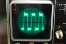
pin 3 U13A and pin 3 U14A (picture) near identical.
pin 5 and 6 of the same IC's: block cyclic changing in width. Is that normal?
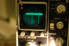
pin 3 U15: picture
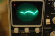
Pll sound output gives the sawthoot but mixed with another wave.
I'll check it again.
JP
Thank you for your help, I feel we are close to diagnostic it.
all power supplies, with the scope, and it's 5V DC with absolutely no signs of oscillation, also
Voltages OK and no trace of oscillations.
what kind of cap did you apply on the reg's output? 10uF solid polimer - might be a problem]
Vishay solid aluminium.
And there they are both the ~ 700 KHz 5v square wave signals on the output of the two counters/dividers;
pin 3 U13A and pin 3 U14A (picture) near identical.
pin 5 and 6 of the same IC's: block cyclic changing in width. Is that normal?
pin 3 U15: picture
Pll sound output gives the sawthoot but mixed with another wave.
Also there might be a problem with the filters time constants, so your PLL loop is not stable. This should not be a problem if all the main filter caps
I'll check it again.
JP
Jp,
As far as I see everything is functional. You see a changing duty cycle on those 5; 6 pins because the PLL is not in lock; that is, the phase between the two clocks is not fixed, slowly shifting. [At least hope that it's slow - what is the freq. of that "audio" pll output signal?][what is the time setting in that pic? [not the 705kHz one]]
So for me it continues to be the previous two cases: most probably You have a too great frequency difference between the VCXO local clock and the external CD drive. So the VCXO & PLL is "trying to catch", "chasing" the incoming clock, but can not get close enough.
I suppose R170 is 1.1Mohm as prescribed? Both ends of C171 should see high impedance [500kohm] towards ground, and all the caps from C171 to C177 should actually have zero leakage [no faulty ones there?]
At this point one good trial would be to install / replace the original clock in one of your drives with an external, simple HC04 one. And adjust / pull the clock frequency of this new, external one by adding small tuning capacitances. [You can continue to use the original crystals in the new clck ]
When testing, you should leave more than ~20 secs for the PLL to lock. The leds should start blinking first and then go off.
Ciao, George
Hi Georges
It's me again.
The timebase for the LF signal on PLL audio was about 20mS/division.
I 'll construct a HC 04 oscillator a nd try your suggestion . Do I have to change the two small capacitors to adapt the oscllation frequency? I have a spare X tal available.
I tried to feed the DAC with a 48 kHz signal from a DVD player.
Now the LED doesn't change colours from red to green but
stays red. The CS8412 sets the ERF
CONTINUE
The CS8412 setsthe ERF to low and red indicates frequency too low? I tried this for curiosity.
Please can you give me t he sch ematic of th e oscillator, I don't find it.
I find several MOhm?
Thank you for your efforts
JP
The CS8412 setsthe ERF to low and red indicates frequency too low? I tried this for curiosity.
Please can you give me t he sch ematic of th e oscillator, I don't find it.
suppose R170 is 1.1Mohm as prescribed? Both ends of C171 should see high impedance [500kohm] towards ground, and
I find several MOhm?
Thank you for your efforts
JP
JP,
Heck, I have to say it really bugs me, Your problem. Also I was thinking that though it is really possible that You are just highly unfortunate with your drives, but still - In my case I have experienced at about 10 - 15 % of my trials with CD players ended bad, but all the rest was just good.
So, it also can be that something is really wrong and we just did not find that bug yet..
On pins of C171 we should measure exactly 500Kohm, IF the circuit is active [ON]. If it is off, then it very possibly is ~some Mohm. So your result is good. The main thing is that it's high, no leakage which could upset the filter.
Another thing came into mind: You wrote to have seen at about 2.5 V on the output of the TLC271. Now, I think if it's out of lock, then it should hunt up / down, so on the scope You should be able to see a signal changing between 0 and ~4.5 - 4.8V [IF the 6 volt DC supply is present on pin 7] Could You make a scope photo on the
- output of TLC 271 [ PIN 6]
- on the input of the VCXO [the other end of the R178]
Maybe with spdif cable both connected / unconnected. Question is,
is the output capable sweeping freely up/down or gets stuck somewhere?
And Rfbrw is right, obviously this DAC works only with 44.1K.
Though why ERF went high, is a good question..
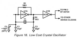
Finally, the osc. schematics. It's a bog standard application, we don't want a good clock at this moment, just a working one ..
You can start with 22 - 33 pF caps, and adjust as shown.
The output of it should go to the Xtal pins in the original osc., possibly across a small [50 100 ohm] resistor.
TO THE INPUT PIN there! [The pin on which the scope shows a small sinusoidal. The other one, the output of the original driver/amp will show a higher level ~ square signal.]
Original XTAL should be removed.
But first let's try to find the bug..
Ciao, George
Heck, I have to say it really bugs me, Your problem. Also I was thinking that though it is really possible that You are just highly unfortunate with your drives, but still - In my case I have experienced at about 10 - 15 % of my trials with CD players ended bad, but all the rest was just good.
So, it also can be that something is really wrong and we just did not find that bug yet..
On pins of C171 we should measure exactly 500Kohm, IF the circuit is active [ON]. If it is off, then it very possibly is ~some Mohm. So your result is good. The main thing is that it's high, no leakage which could upset the filter.
Another thing came into mind: You wrote to have seen at about 2.5 V on the output of the TLC271. Now, I think if it's out of lock, then it should hunt up / down, so on the scope You should be able to see a signal changing between 0 and ~4.5 - 4.8V [IF the 6 volt DC supply is present on pin 7] Could You make a scope photo on the
- output of TLC 271 [ PIN 6]
- on the input of the VCXO [the other end of the R178]
Maybe with spdif cable both connected / unconnected. Question is,
is the output capable sweeping freely up/down or gets stuck somewhere?
And Rfbrw is right, obviously this DAC works only with 44.1K.
Though why ERF went high, is a good question..
Finally, the osc. schematics. It's a bog standard application, we don't want a good clock at this moment, just a working one ..
You can start with 22 - 33 pF caps, and adjust as shown.
The output of it should go to the Xtal pins in the original osc., possibly across a small [50 100 ohm] resistor.
TO THE INPUT PIN there! [The pin on which the scope shows a small sinusoidal. The other one, the output of the original driver/amp will show a higher level ~ square signal.]
Original XTAL should be removed.
But first let's try to find the bug..
Ciao, George
Attachments
jpfastre said:The PLL doesn't lock in the Tentlabs DAC (Tube DAC). I changed already U11, U12, U13, U14, U15, U17 without result. I checked the resistors and capacitors of the PLL circuit. The bicolor LED lights red at the start and lights than alternate green or red.
The output voltage at pin 6 of the TLC251 is a unstable voltage around about 2.5 V. I use the Tentlabs VCXO.
Please help.
Hi JP,
The 2.5V indicates that the loop is working, but not stable. It tends to lock, come to nominal 2.5V at the opamp output, but does not seem to remain stable.
Check all capacitors / values and all connection in the analogue loop, I suspect an error there.
If you don't succeed, you're welcome at the lab in Eindhoven.
best
Also there might be a problem with the filters time constants, so your PLL loop is not stable. This should not be a problem if all the main filter caps
George
We found it.
You we're right about the time constants.
I was searching and testing for the scope pictures you asked for.
There was an invisible print crack between R176 and C176.
I bridged it with a wire and the DAC locks.
Many thanks for your help.
Regards.
JP
- Status
- This old topic is closed. If you want to reopen this topic, contact a moderator using the "Report Post" button.
- Home
- Source & Line
- Digital Source
- PLL doesn't lock in Tentlabs DAC