So, I'm desiging a DAC which will use PCM1794, and I want to have balanced output. I'm trying decide between using fully differential op amps (e.g. OPA1632 or AD8138) or separate op amps for + and - signals (possibly AD8065/6 or AD8610/20). Does anyone have specific suggestions/advice/experience doing this? It seems there are not too many balanced designs out there.
There's a discussion about this topic in the Pass forum:
http://www.diyaudio.com/forums/showthread.php?s=&threadid=78968
http://www.diyaudio.com/forums/showthread.php?s=&threadid=78968
balanced outputs
Hi, ezkcdude,
I found this link:
http://sound.westhost.com/balance.htm
It contains several balanced designs using single OP-amps
Hi, ezkcdude,
I found this link:
http://sound.westhost.com/balance.htm
It contains several balanced designs using single OP-amps
ece, just read that link. I think maybe the balanced line receiver approach might be the best for me. It's a single-ended output, but probably has most of the benefits of a balanced design anyway (i.e. common mode rejection). Since I won't be driving very long cables, maybe it's not essential to have true balanced outputs. Also, it appears like a very simple design, and is already suggested in several data sheets that I've been looking at.
Banned
Joined 2002
There's a very simple circuit diagram for balanced to single-ended conversion in AD's "Data Conversion Handbook" (Fig. 6.70 on p. 417). I think I may just try this design first, at least, in the prototyping stage. I've attached a schematic of the I/V stage with the PCM1794, if anyone's interested. I should note that I've drawn it using AD8620, which is a dual op amp. This is a convenient choice because you can get a Brown Dog pre-mounted DIP.
Attachments
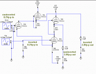
If you like tubes, here's a balanced in and balanced output DAC circuit using tubes. The 6111 is somewhat similar to a 12AU7. Low mu triode. The voltage sources represent the DAC outputs feeding the 150 ohm resistors as an IV converter. The rest of the tube circuit is a differential pair, with a pair of "SRPP" type output driver circuits.
Attachments
In the diagram I gave in my last post, the ratio of the resistor values gives the voltage gain. My question is how do you choose the actual resistor values? See the attached diagram. I've drawn the same circuit, but with different resistor values, each theoretically giving the same gain. What are the pros and cons of choosing lower valued vs. higher valued resistors in this op amp circuit? I have no idea.
Attachments
- Status
- This old topic is closed. If you want to reopen this topic, contact a moderator using the "Report Post" button.
- Home
- Source & Line
- Digital Source
- Suggestions for balanced DAC output?
