Hey guys my first post ")
I was wondering if you expert people could help, my DAC uses two 2uf output coupling capacitors, what would happen if I’d get rid of them and replace them with simple wire? Would it be safe? What would the effects be?
Or for a second option, how much smaller can their value be and what would be the sonic effects?
I have seen some designs where they got rid of them? And I was wondering if that would be possible in any DAC.
Thx for the help
francesco
lohk said:Why not buy two Blackgates?
Because there are better caps ....
Overpriced ....
i have already bought two mundorf silverg gold
but i was wondering if no cap would be better the audio note 4 and 5 do not have any
i'll try to check if there is any dc as you suggested lohk
thxs a lot for the help
what happens changing the values to smaller ones? is this going to effect only the bass or else?
francesco
but i was wondering if no cap would be better the audio note 4 and 5 do not have any
i'll try to check if there is any dc as you suggested lohk
thxs a lot for the help
what happens changing the values to smaller ones? is this going to effect only the bass or else?
francesco
Sure it is. sounds lovely already, but i am sure it can be much improved.
Any advice on how to mod the dac would be more than welcome. i already realised -thxs to your responses- that that was not a wise idea.
What about smaller values? Like 1.5 instead of 2uf? What difference would they make?
francesco
Any advice on how to mod the dac would be more than welcome. i already realised -thxs to your responses- that that was not a wise idea.
What about smaller values? Like 1.5 instead of 2uf? What difference would they make?
francesco
Well if there is a resistor to ground after the cap lowering the capacitor rolls off the bass.
If so it depends on the value of the resistor, for example in my player the cap is 1uf and the resistor 33K which is ok, any lower gentle rolls off bass (not such a bad thing but it can cause phase error)
If so it depends on the value of the resistor, for example in my player the cap is 1uf and the resistor 33K which is ok, any lower gentle rolls off bass (not such a bad thing but it can cause phase error)
Just to clarify what others have said, to figure out the smallest cap size that makes sense, use the formula
C = 1/(2 * pi * F * R)
where C is the cap size, F is the 3dB rolloff frequency you are willing to accept, and R is the impedence (resistance) seen by the cap. F should probably be 2Hz or smaller as you will get phase distortions for a full decade above the 3dB point. R is the input impedence of the next stage in parallel with the resistor to ground of this stage.
So, assume that there is a 50K resistor to ground, and the input impedence of your preamp is 50K, then
C = 1/(2 * pi * 2 * 25K) so you would want a cap size of 3.2uF.
Note that you can reduce the size cap you need slightly by increasing the resistor to ground after the cap to something liek 100K though too high can cause noise. Also, if your stereo only reproduced frequencied down to something like 50Hz, then you can use a higher 3dB point (5Hz in this case.)
-d
You should think fast switching soft recovery diodes, 4 of them for each bridge rectifier. There are 6 bridge rectifiers in total, so you'll need 24 diodes. This will improve the sound a lot, but requires careful soldering and implementation because you are not allowed to make mistakes here.
Extreme_Boky
Extreme_Boky
thxs guys
Extreme_Boky so i have been told! that the diodes would make a big difference, i know about the cheaper solution with 4 diodes x rectifier
Schematics here
http://www.hificollective.co.uk/pdf/diode.pdf
However is there a cleaner solution, although might be more expensive, to do this with one single piece to replace the
PEC 0483 GBU 4K
that i have inside now?
or any other suggestion about the DAC72?
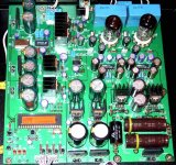
I have attached a picture of the board (also in another thread but no replies there)
Extreme_Boky so i have been told! that the diodes would make a big difference, i know about the cheaper solution with 4 diodes x rectifier
Schematics here
http://www.hificollective.co.uk/pdf/diode.pdf
However is there a cleaner solution, although might be more expensive, to do this with one single piece to replace the
PEC 0483 GBU 4K
that i have inside now?
or any other suggestion about the DAC72?
I have attached a picture of the board (also in another thread but no replies there)
Attachments
lightmaster said:However is there a cleaner solution, although might be more expensive
http://www.partsconnexion.com/catalog/semiconductors.html
Yes, that could work, but is damn expensive!!!
For low voltage levels (up to 30V AC) there's only one diode I use: BAT42. Careful! they are very sensitive to back EM voltages (ON – OFF), so better leave everything ON all the time (except valves' power supply that should be swiched off when not in use, which need higher voltage diodes…) Try RURP 3060 for valves supply.
Extreme_Boky
- Status
- This old topic is closed. If you want to reopen this topic, contact a moderator using the "Report Post" button.
- Home
- Source & Line
- Digital Source
- taking out Output coupling capacitors in a dac