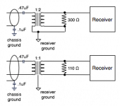
i'm trying to assimilate information from a couple of sources to figure out what i'm sure is something simple: using isolation transformers for the input(s) to a digital receiver. this schematic is almost exactly the one from the CS8416 data sheet for balanced digital input (bottom) and a hacked together one based on the CS8416 sheet and the scientific conversion aes1998 paper for unbalanced digital input (top).
the balanced version assumes a scientific conversion SC947-02 transformer. the unbalanced versions assumed a SC982-04 transformer.
since the unbalanced version is the one i hacked together, it is most likely wrong and i would really appreciate suggestions from folks on what is wrong with it.
thanks,
bb
Attachments
- Status
- This old topic is closed. If you want to reopen this topic, contact a moderator using the "Report Post" button.