I am hoping to tap into an i2s signal in my Harmon Kardon CDP. However, I am not sure how to extract it from a CXD1167 chip. There is a prior thread that mentions the CXD1167, but it does not indicate which pins provide the outputs. I do not think the “resister” clue mentioned in that thread helps me for the following reasons:
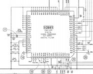
According to the Tech Manual for the CDP, the CXD1167 D.S.P. feeds a “serial” signal to a SM5871AN dac chip. The specifications state that the SM5871AN is a dual single bit converter. The schematic for the CDP shows 3 lines from the D.S.P. (pins 76 (DA14), 78 (DA16) and 80 (LRCK) going to the dac after each passes through a 470 Ohm resister. These lines attach to pins 9 (BCK1), 10 (DIN) and 8 (LRC1), respectively, of the dac. The data sheet for the dac describes pin 10 (DIN) as “serial data input.” The data sheet contains a description of the “Audio Data Input” as “The digital audio data is input as DIN in 2s complement, msb-first, 16 bit serial format.” The Tech Manual for the CDP states that “the signals are output as 16 bit digital signals from pins 76, 78, and 80 of [the D.S.P.] and fed to the D/A converter. In this case, EFM demodulation, error correction, and serial/parallel conversion are performed by the internal circuitry of [the D.S.P.].” I assume the “serial/parallel conversion” means that the data line is not i2s. Might there be a different pin on the D.S.P. that outputs data in parallel format? I have searched the web and cannot find any data sheets for the D.S.P. (apparently it is a SONY component). Is anyone familiar with this chip?
The CDP also has an optical out. I note that the optical device contains an 8.2K resister in parallel with a .022 uF capacitor in front of the transmitter. (The optical device appears to be an HK part as the parts list describes it only as “E/O PLT102, Converter, Digital Output”.) The optical device is connected to pins 27 (DOTX) and 73 (VDD) of the D.S.P. and ground. Does that suggest that those lines are SPDIF? If so, can I just tap in before the optical device and add a coax jack? Any suggestions would be greatly appreciated.
Thanks, that helps quite a bit.
Am I correct that pin 27 of the CXD1167 provides a TTL signal and that what I am trying to do is convert the TTL to SPDIF? And that Katapum's output will accomplish this? If so, do I simply connect Katapum's J1 to pin 27, or do I need to add a voltage source as well?
Am I correct that pin 27 of the CXD1167 provides a TTL signal and that what I am trying to do is convert the TTL to SPDIF? And that Katapum's output will accomplish this? If so, do I simply connect Katapum's J1 to pin 27, or do I need to add a voltage source as well?
jazzzman said:Thanks, that helps quite a bit.
Am I correct that pin 27 of the CXD1167 provides a TTL signal and that what I am trying to do is convert the TTL to SPDIF? And that Katapum's output will accomplish this? If so, do I simply connect Katapum's J1 to pin 27, or do I need to add a voltage source as well?
TTL and SPDIF are separate issues but Katapum's circuit is all you need.
- Home
- Source & Line
- Digital Source
- Modify HK CDP to output i2s and coax spdif?