I got a hold of a Magneto Optical Disk Recorder (AKAI DD1000). It seems to be a very obsolete format and the machine actually doesn't seem to work. Someone told me that the A/D converters are pretty good, though. So, I'm wondering if anyone would be able to tell me if it would be possible, or how difficult it would be for someone like myself, who doesn't have alot of experience with electronics, to remove the the A/D converters and make a sort of home made stand alone unit. Any suggestions? Has anyone ever done something similar? Or is what I'm asking impossible?
Thanks,
DDA
Thanks,
DDA
dda said:I got a hold of a Magneto Optical Disk Recorder (AKAI DD1000). It seems to be a very obsolete format and the machine actually doesn't seem to work. Someone told me that the A/D converters are pretty good, though. So, I'm wondering if anyone would be able to tell me if it would be possible, or how difficult it would be for someone like myself, who doesn't have alot of experience with electronics, to remove the the A/D converters and make a sort of home made stand alone unit. Any suggestions? Has anyone ever done something similar? Or is what I'm asking impossible?
Thanks,
DDA
1. Do you have the service manual or at least a schematic ?
2. Do you know the part number of the A/D chip(s)?
The AK5326 sounds about right. It's a fairly old dac but if you like its sound I suppose that does not matter.
What does matter is what you intend to record on. You may need to add a reference input or output. If the DD1000 does not already have a digital output things are going to get quite involved. Back to the AK5326. Connected to pin23 should be a clock signal. Look around and see if there is some kind of metal can with a frequency printed on it. It could be anything between 11 and 33 MHz.
What does matter is what you intend to record on. You may need to add a reference input or output. If the DD1000 does not already have a digital output things are going to get quite involved. Back to the AK5326. Connected to pin23 should be a clock signal. Look around and see if there is some kind of metal can with a frequency printed on it. It could be anything between 11 and 33 MHz.
Yeah. Actually I don't really know if the thing sounds good. The person who owned it before me said it did. I think it was a high end machine for it's time.
Anyhow,
It does have a digital out (AES/EBU). And you are right the AK5326 is in a socket and pulls out. How are the pins numbered? How do I find pin 23?
Didn't see any metal can with a frequency marked on it.
Anyhow,
It does have a digital out (AES/EBU). And you are right the AK5326 is in a socket and pulls out. How are the pins numbered? How do I find pin 23?
Didn't see any metal can with a frequency marked on it.
If it has a digital output then you have three choices, use it as is, using the digital output, add a reference input or salvage the parts and build an ADC from scratch.
Re the clock. You can identify pin one by either a dot or a dimple in one corner or a u-shaped notch on the ic package. Pin 1 will be to the left of the notch with pin28 to the right. Also look out for the AES/EBU chip as well.It may be a CS8402 or a CX or a TC something.
Re the clock. You can identify pin one by either a dot or a dimple in one corner or a u-shaped notch on the ic package. Pin 1 will be to the left of the notch with pin28 to the right. Also look out for the AES/EBU chip as well.It may be a CS8402 or a CX or a TC something.
Re: the three possibilities
1) Using it as is: Seeing as the machine doesn't work, would that be possible?
2) Adding a reference input: Not sure I know what you mean by that
3) Building from scratch
Re: the clock
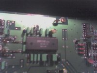
I think I managed to find pin 23 and follow it's path. It seems to be connected to a component which I cannot identify (forgive my inexperience). It is marked FL10 on the circuit board. On the component itself, the only thing I can read is: 100V. It has three pins.
The other end of this comonent is connected to a chip marked:
HD74HC14P
I think the AES/EBU chip might be this: TDK CIT0723DIP-340B
Does that seem right?
By the way thanks for all your help. I appreciate it.
Didier
1) Using it as is: Seeing as the machine doesn't work, would that be possible?
2) Adding a reference input: Not sure I know what you mean by that
3) Building from scratch
Re: the clock
I think I managed to find pin 23 and follow it's path. It seems to be connected to a component which I cannot identify (forgive my inexperience). It is marked FL10 on the circuit board. On the component itself, the only thing I can read is: 100V. It has three pins.
The other end of this comonent is connected to a chip marked:
HD74HC14P
I think the AES/EBU chip might be this: TDK CIT0723DIP-340B
Does that seem right?
By the way thanks for all your help. I appreciate it.
Didier
Sounds like there is a ceramic resonator, which does much the same thing as a clock crystal. What colour is it?
Building from scratch might be the way to go but that depends on what you can and cannot do. At its most basic, you will probably need no more than 5/6 chips for an ADC plus the power supply.
Re the reference input. An ADC needs to be synchronized to the recording device for best performance. How you go about doing this depends on what you you intend to record to. There are 4 possibilities. No sync. ADC is master and sends sync signal to recording device. Recording device is master and sends sync signal to ADC. ADC and recording both receive common signal from external device i.e. a SPG (Sync Pulse Generator).
The thing is orange. There are quite a few of them. I would say there might be 20 in the whole unit. I'm attaching a picture of some of them. (again, sorry the picture is terrible)
As far as the synch is concerned, would it be possible to build it with the capability to switch between internal and external synch? There seems to be an video/word synch input on the unit already.
As far as the synch is concerned, would it be possible to build it with the capability to switch between internal and external synch? There seems to be an video/word synch input on the unit already.
Attachments
dda said:The thing is orange. There are quite a few of them. I would say there might be 20 in the whole unit. I'm attaching a picture of some of them. (again, sorry the picture is terrible)
We can come back those later
As far as the synch is concerned, would it be possible to build it with the capability to switch between internal and external synch? There seems to be an video/word synch input on the unit already.
At this point it will be useful to find out exactly where the fault lies as it seems everything needed is already present and, if possible, it would be best to use the original case. If the fault lies in the MO section, it might be possible to disconnect that section and use the rest
It is possible to add an internal clock for sync purposes but it might then be necessary to send that clock or a clock derived from it to the recording device.
- Status
- This old topic is closed. If you want to reopen this topic, contact a moderator using the "Report Post" button.
- Home
- Source & Line
- Digital Source
- Removing A/D converters from obsolete machine