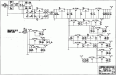
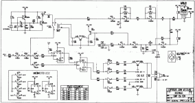
John I have a Discmagic 1 and it's got a problem, I hope you can point me in the right direction. It has 14.9mhz that I measured on the clock instead of 16.9mhz sometimes it reads and plays, most times it does'nt spin up and just says disc in the readout after about 5 seconds of not spining up.
One of the two regulators with sheet metal aluminimum heat sinks on the clock/output board, that are side by side almost touching the rear panel is very hot, the other is warm, is this natural?
Cheers George
One of the two regulators with sheet metal aluminimum heat sinks on the clock/output board, that are side by side almost touching the rear panel is very hot, the other is warm, is this natural?
Cheers George
George,
Both regulators on the PCB should be at the same temperature - the fact that one is getting hotter then the other, and that the Clock Frequency is incorrect suggest a fault somewhere on the board bringing down the PSU rail.
Thanks to Dan on this Forum - I can forward to the Circuit Diagram of the DOTX board - PM me if you need it.
John
John or anyone else. Question on this transports power supply for the clock/output board.
Why is the 12v negative regulator U1 output being shorted to ground via the 30mh winding of the L2 choke, it is very hot and is only giving .5v output, because of the near short.
Cheers George
Why is the 12v negative regulator U1 output being shorted to ground via the 30mh winding of the L2 choke, it is very hot and is only giving .5v output, because of the near short.
Cheers George
Attachments
George,
In fact the -12V is not being shorted to ground - its and error on the Cambridge audio circuit Diagram - "Ground" for the board is taken AFTER the CM choke - you should see 12V after the 7812 & 5V after the 7805’s - if one of these supplies is "low" then you need to find out why.
Even if the one of the supplies is low - I would be very surprised if the XO circuit was oscillating at such a low frequency (you said 14.9MHz), I would suspect measurement error - or failure of the Crystal (did you change the crystal type?). The XO circuit is standard Colpitts – not much to go wrong here.
If the problem is with the DOTX output board, then have a suspicion that somebody’s tried to ‘Upgrade” the clock or PSU and messed things up –has this unit been modified in anyway?
I would confirm the Clock Frequency measurements again – if indeed it’s correct, then I would look around the servo board, these units are more then 10 years old – and the Sanyo / Sony laser and chipset was never the best – developed before CD/R or CDRW, or even longer playing CD’s.
If this unit has been modified, check that the small ceramic “RF decoupling” Caps are still in-place between the servo PCB and the copper shielding.
Best of luck in repairing the unit,
John
Come on George, Pls. give some credit here, No designer is ever going to be crazy enough to needlessly short a regulator to ground via a 4 ohm short - Why?
I repeat again: -
"the -12V is NOT being shorted to ground - its and error on the Cambridge audio circuit Diagram - "Ground" for the board is taken AFTER the CM choke"
The PCB "area" before the CM choke is Isolated from the "Ground plane" after the CM choke - if this is not the case, then there is a short-circuit, but its not by design - it’s a component fault somewhere on the PCB.
John
Sorry John, I did not mean to imply that you designed this error into the prodution models, but maybe the person who owned this unit gave it an earth thinking it should be there because of the diagram. I've yet to dismatle it to have a look under the board to see why it may go to earth. I've measured it from the top and sure enough it does go to earth after the choke. I'll keep you posted.
Cheers George
Cheers George
Yes this unit has be looked at before, many times by the look of the screws and solder jobs, it's the 7912 reg that's getting hot, the crystal looks original and all the components around it, and it is giving 16odd fluctuating mhz, my new second hand Fluke digital counter is of and needs a recal after checking another 16mhz transport it also read 14mhz. So the cyrstal is ok, now to find out why the choke is getting earth on the other side of it.
Cheers George
Cheers George
George,
Before you spend too much time searching for a fault that may not exist - with the unit powered-off, check the resistance between the transformer centre tap (incorrectly indicated as GND on the circuit diagram. and the Ground plane AFTER the common mode inductor - say the Ground tab on the 7812 Regulator on the black heatsink - if a short does not exsist between these nodes then its OK.
I would suspect the disc reading problems you describe have nothing to do with the DOTX board (the Digital output board), but a worn laser (if still original, then 10 years is very good going for this laser head).
John
George,
Yes that’s incorrect, and if you measurements are correct (Just to confirm that we are talking about the GND connection on U3 - 7812 on the Black heatsink), then that’s why the 7912 is getting so hot.
I would look for a failed Capacitor around U1, C1 or C14 – the 100n Ceramic Caps – there’s not much else – provided that U1 the 7912 has not failed internally.
John
Because of the very high current draw at the moment, the 5+VA1 for the clock circuit is also from this supply and maybe that's why I have such a large fluctuation in the 16mhz clock frequency
and sometime it can'nt read the disc when it's way off, would this be an explanation John?
And John I'm sure someone has played with the two trimpots around the clock can you tell me how to adjust them and what they do?
Cheers George
and sometime it can'nt read the disc when it's way off, would this be an explanation John?
And John I'm sure someone has played with the two trimpots around the clock can you tell me how to adjust them and what they do?
Cheers George
Attachments
The C25 sets the frequency, VR1 sets the M:S ratio.
Frequency will not be badly off - even with low PSU rails - the servo board is petty intolerant to absolute Frequency - pitch controls on DJ CD players work by changing the MCLK Frequency over a large range.
I suspect your playback problems are due to a worn laser - however I could be wrong,
John
Frequency will not be badly off - even with low PSU rails - the servo board is petty intolerant to absolute Frequency - pitch controls on DJ CD players work by changing the MCLK Frequency over a large range.
I suspect your playback problems are due to a worn laser - however I could be wrong,
John
- Status
- This old topic is closed. If you want to reopen this topic, contact a moderator using the "Report Post" button.
- Home
- Source & Line
- Digital Source
- Pinging JohnW

