I was told that small SMD capacitors (small rectangular capacitors)on PCB of CDROM can be removed for better sound. Have anyone try this and I would like to learn the thoughts. Can anyone tell me where I can find schematics of CDROM so that I can check which capacitors I can remove?

Well,
the SMD capacitors provide the best theoretical noise attenuation / decoupling. No legs, and if the ground plane area is maximized and with no noise, they work wonders. The problem is finding”nice” sounding ones...
Someone here on forums reported Murata 22uF SMD ceramic as excellent choice....
Extreme_Boky
Thanks Extreme_Boky, frdchang and DSP_Geek for quick replies.
However, I thought the ICs are for servo control and laser control. Would appreciate if DSP_Geek can provide further details.
Extreme_Boky, do you mean that I should keep the ceramic caps?? Or I should replace them with good ones as you suggested (Murata 22uF SMD ceramic).
However, I thought the ICs are for servo control and laser control. Would appreciate if DSP_Geek can provide further details.
Extreme_Boky, do you mean that I should keep the ceramic caps?? Or I should replace them with good ones as you suggested (Murata 22uF SMD ceramic).
rickronn said:Thanks Extreme_Boky, frdchang and DSP_Geek for quick replies.
However, I thought the ICs are for servo control and laser control. Would appreciate if DSP_Geek can provide further details.
Extreme_Boky, do you mean that I should keep the ceramic caps?? Or I should replace them with good ones as you suggested (Murata 22uF SMD ceramic).
You do realize I was *joking*, right?
Anyway, the caps are on the circuit board for a reason: they keep the supply voltage from bouncing around. Removing them could cause the CD-ROM to work intermittently or not at all.
Jocko,
I accept that a 22uF cap sucks big time quality wise.. But where the quantity maybe counts more than the quality.. [digital]
It would be good to know, if You have any seriuos objections. Because also me makes part of that world who has been lured in..
And had spent money on such things..
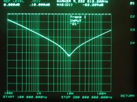
Though I got only the 10uF ones - I'm a modest guy. Also some 1uF, about this later. They are damned small, for testing them I had to make a better jig.
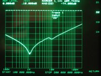
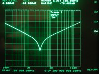
Ecco l'impedance of a common 100nF/50V x7r:
I accept that a 22uF cap sucks big time quality wise.. But where the quantity maybe counts more than the quality.. [digital]
It would be good to know, if You have any seriuos objections. Because also me makes part of that world who has been lured in..
And had spent money on such things..
Though I got only the 10uF ones - I'm a modest guy. Also some 1uF, about this later. They are damned small, for testing them I had to make a better jig.
Ecco l'impedance of a common 100nF/50V x7r:
Attachments
Consider this you have been told as a rumour, not more. This is like "I have been told that resistors are bad for the sound and it get better if they are removed". You see how silly this is?rickronn said:I was told that small SMD capacitors (small rectangular capacitors)on PCB of CDROM can be removed for better sound.
What you must ask yourself is:
What task has this capacitor and what are the requirements?
Can I find an another part which has better performance of those parameters which are important here. If you don't have the anwers you are
 and the results can be whatever.
Jocko,
I don't know.. I have a lurking sensation that I might have been influenced at the critical moment of decision.. by some notonlyclock-mongers insisting on it since forever..
Yeah, it's worse than television commercials..
Ciao, George
I notice that you did not have a Z5U caps, did you?? I wonder why.
I don't know.. I have a lurking sensation that I might have been influenced at the critical moment of decision.. by some notonlyclock-mongers insisting on it since forever..
Yeah, it's worse than television commercials..
Ciao, George
I use these big 1206/1210 MLCC's all the time.Jocko Homo said:Why do you think that a 22 uF ceramic cap could possibly be good?
Jocko
They're smaller/denser than tantalums, the board stuffing shop can't put them in backwards, they have outstanding ESL/ESR, high current handling which makes them great for small SMPS, the price is comparable... and none of the environmental **** associated with tantalum mining is involved.
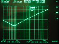
I strongly suggest using X5R dielectrics... the capacitance on Z5U/Y5V parts takes a big dive when you apply volts. And these high capacitance parts are best used for rail decoupling, not component decoupling - keep plenty of 0603, 0.01-0.1uF close to the pins of your fast chips.
So those 22 uF are a decent mix then? Not that Z5U garbage?
Yes, look at the capacitance vs V curve if there is one. Nasty, nasty stuff. Not good for anything.
BTW......I hate tantalums more than you do, but for other reasons. Would you care to guess how many hours that I have spent, trying to fix dead 70 MHz IF strips, because some damn tantalum, or crappy monolythic ceramic, cap failed and took down the supply rail.
Jocko
I feel your pain. You need my "bad tantalum tool" - a Xantrex HPD-15-20 power supply.
Set the volts to 5V or whatever, dial the current down to zero and connect it across your rail. Then increase the current until the offending tantalum starts glowing - as soon as this happens, kill the amps before the thing goes exothermic and burns a hole in your board.
Works great for charging batteries too. Not bad for $20 off ebay.
increase the current until the offending tantalum starts glowing
I use the same technic
Extreme_Boky
- Status
- This old topic is closed. If you want to reopen this topic, contact a moderator using the "Report Post" button.
- Home
- Source & Line
- Digital Source
- Get Rid of the Small SMD Capacitors on CDROM for Better Sound