drobert said:Hi,
It is sure?
I don't understand something.
If I connect the AD1865 output to R8. The output of the AD will be about 3,3V.
Robert
Sure, it is not right!!!
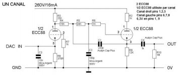
The I/U resistor in this shematic is the 22 kohms
ad1865 1 ma full scale will give 22 Volts at the output of this circuit (called common grid).
There is a problem with this common grid : the dac input is not 0V :
then the ad1865 can blow.
You have to reference the 375 ohms resistor to a negative supply, to have 0V on the dac input.
Go to this post and the rest of this thread :
http://www.diyaudio.com/forums/showthread.php?postid=696684#post696684
Philippe
Konnichiwa,
Well, not for the AD1865, but then, it was explicitly designed for one DAC chip and ONE only, simply because this DAC chip will not work with the normal solutions.
No, it is not. The U/I Resistor is 375R in parallel with around 800R, so around 250R. This with the intended DAC which has when used as instructed with the original version of the schematic 2mA Peak-Peak full scale output current will give a voltage of 500mV Peak-Peak on the ECC88 Cathode, which as observed works as grounded grid amplifier.
All in all the circuit used with the DAC it is designed for gives a bit above 2V for full scale.
That is intentional, the DAC this output stage is designed for likes to have it's output at 3.3V, not 0V and will not work well otherwise.
Sayonara
philbyx said:Sure, it is not right!!!
Well, not for the AD1865, but then, it was explicitly designed for one DAC chip and ONE only, simply because this DAC chip will not work with the normal solutions.
philbyx said:The I/U resistor in this shematic is the 22 kohms
No, it is not. The U/I Resistor is 375R in parallel with around 800R, so around 250R. This with the intended DAC which has when used as instructed with the original version of the schematic 2mA Peak-Peak full scale output current will give a voltage of 500mV Peak-Peak on the ECC88 Cathode, which as observed works as grounded grid amplifier.
All in all the circuit used with the DAC it is designed for gives a bit above 2V for full scale.
philbyx said:There is a problem with this common grid : the dac input is not 0V :
That is intentional, the DAC this output stage is designed for likes to have it's output at 3.3V, not 0V and will not work well otherwise.
Sayonara
Konnichiwa,
Not really, you may be able to adapt it, but changes would be needed. But given that TDA1545 this circuit is designed for is so dramatically superior to the TDA1543 sonically and given that it is readily available for the same sort of money as a 1543, I'd ask "Why bother with 1543?".
The key attraction of the 1543 is that it actually works very well with just a resistor as I/V and an output coupling capacitor to give nearly 2V RMS @ 0dbfs, in other words, no active output stage. Adding an analogue stage only detracts from that.
Sayonara
drobert said:can I use this schematic with TDA1543?
Not really, you may be able to adapt it, but changes would be needed. But given that TDA1545 this circuit is designed for is so dramatically superior to the TDA1543 sonically and given that it is readily available for the same sort of money as a 1543, I'd ask "Why bother with 1543?".
The key attraction of the 1543 is that it actually works very well with just a resistor as I/V and an output coupling capacitor to give nearly 2V RMS @ 0dbfs, in other words, no active output stage. Adding an analogue stage only detracts from that.
Sayonara
Kuei Yang Wang said:Konnichiwa,
Well, not for the AD1865, but then, it was explicitly designed for one DAC chip and ONE only, simply because this DAC chip will not work with the normal solutions.
No, it is not. The U/I Resistor is 375R in parallel with around 800R, so around 250R. This with the intended DAC which has when used as instructed with the original version of the schematic 2mA Peak-Peak full scale output current will give a voltage of 500mV Peak-Peak on the ECC88 Cathode, which as observed works as grounded grid amplifier.
Sayonara
Bonjour
I agree with you because this 250 R is in fact the input impedance. Then the dac current will flow in this impedance and will give this voltage (2vpp) on it.
But replace the 375 R with a constant current source, and then, the I/U resistor will be the plate resistor.
Feed 1 ma on the cathode, you will find 1 ma in the plate Resistance, then U = 1ma x plate resistance.
http://www.tubecad.com/april_may2001/page24.html
http://www.diyaudio.com/forums/showthread.php?postid=696684#post696684
Au revoir
")
Philippe
Bonjour,
Yet I designed and published the circuit using a Resistor and not a CCS (for very good reasons as well). BTW, when I published the circuit it was also made clear that it is to match the TDA1545 in a Philips CD-720/21/22/23 and included some other notes, all in German.
It is a poor idea to just copy something without understanding it (and it is not nice to publish others IP without consent or at least attribution), yet it seems a number of Website owners seem happy and even keen to do exactly that.
As for the theory of such circuits, I am reasonably well versed in it, thank you very much.
At any extent, as is the Circuit is designed for the TDA1545 and ONLY for the 1545 and non else and it works as intended in that application and rather well if I may say so myself.
See Ya....
philbyx said:I agree with you because this 250 R is in fact the input impedance. Then the dac current will flow in this impedance and will give this voltage (2vpp) on it. But replace the 375 R with a constant current source, and then, the I/U resistor will be the plate resistor.
Yet I designed and published the circuit using a Resistor and not a CCS (for very good reasons as well). BTW, when I published the circuit it was also made clear that it is to match the TDA1545 in a Philips CD-720/21/22/23 and included some other notes, all in German.
It is a poor idea to just copy something without understanding it (and it is not nice to publish others IP without consent or at least attribution), yet it seems a number of Website owners seem happy and even keen to do exactly that.
As for the theory of such circuits, I am reasonably well versed in it, thank you very much.
At any extent, as is the Circuit is designed for the TDA1545 and ONLY for the 1545 and non else and it works as intended in that application and rather well if I may say so myself.
See Ya....
Kuei Yang Wang said:Bonjour,
Yet I designed and published the circuit using a Resistor and not a CCS (for very good reasons as well). BTW, when I published the circuit it was also made clear that it is to match the TDA1545 in a Philips CD-720/21/22/23 and included some other notes, all in German.
It is a poor idea to just copy something without understanding it (and it is not nice to publish others IP without consent or at least attribution), yet it seems a number of Website owners seem happy and even keen to do exactly that.
As for the theory of such circuits, I am reasonably well versed in it, thank you very much.
At any extent, as is the Circuit is designed for the TDA1545 and ONLY for the 1545 and non else and it works as intended in that application and rather well if I may say so myself.
See Ya....
Hey ! Keep cool!!!
First of all, I didn't copy anything from you, nor I published anything...
The model for the I/V converter I discussed on the other topic is the D1 from Nelson Pass : mosfet common gate, transpose to tube common grid. And it is only simulation...
Don't be so angry.
We absolutly not doubt about your ability as far as tube are concerned. I'm only a learner, and I'm humble.
I beg your pardon, but read again the post, I never criticized your schematics.
Friendly
Philippe
Konnichiwa,
It will not work with the TDA1543, unless the whole operating conditions are adapted to the 1543. I don't have the time and inclination to do so, but feel free if you like....
Sure, you can use common grid with TDA1543, you just need to account for offset current, DAC current and sort out all the other relations.
Sayonara
drobert said:Is it possible to use this schematic with TDA1543 or not?
It will not work with the TDA1543, unless the whole operating conditions are adapted to the 1543. I don't have the time and inclination to do so, but feel free if you like....
drobert said:(or other very simple common grid)
Sure, you can use common grid with TDA1543, you just need to account for offset current, DAC current and sort out all the other relations.
Sayonara
Konnichiwa,
Sorry if it came across as directed at you, it was not. My particular rant was directed at nobody in general or more precisely at those who picked up the schematic (early version too with one or two mistakes) and then republished it without attribution and conetxt (FWIW, the context was a "lets modify the Philips CD-723" group project on a German Discussion board)...
Sayonara
philbyx said:Hey ! Keep cool!!!
Sorry if it came across as directed at you, it was not. My particular rant was directed at nobody in general or more precisely at those who picked up the schematic (early version too with one or two mistakes) and then republished it without attribution and conetxt (FWIW, the context was a "lets modify the Philips CD-723" group project on a German Discussion board)...
Sayonara
Konnichiwa,
No time really. You will have to adjust the first stage cathode and anode resistor to match the DAC in terms of gain, which is a bit of a threehanded juggle as you also need to "clamp" the DAC's output at around 3.3V and the operating point of course gets shifted if the resistors shift.
Sayonara
drobert said:If I like to design this schematic with TDA1543 can you help me?
No time really. You will have to adjust the first stage cathode and anode resistor to match the DAC in terms of gain, which is a bit of a threehanded juggle as you also need to "clamp" the DAC's output at around 3.3V and the operating point of course gets shifted if the resistors shift.
Sayonara
Konnichiwa,
??!!??!!
I am not sure I understand your question.
220mV?
In what sense?
Sayonara
drobert said:OK, but how can I do about 220mv output voltage with TDA1543?
??!!??!!
I am not sure I understand your question.
220mV?
In what sense?
Sayonara
Hello,
May I think badly, but gain of the grounded cathode stage is about 60.
I don't be sure about this, but if I use - for example- 2.2kOhm cathode resistor, 1V voltage change to bring on about 60V change on the anode.
I hope you unerstand me but I told, that my English is wrong.
drobert
May I think badly, but gain of the grounded cathode stage is about 60.
I don't be sure about this, but if I use - for example- 2.2kOhm cathode resistor, 1V voltage change to bring on about 60V change on the anode.
I hope you unerstand me but I told, that my English is wrong.
drobert
- Status
- This old topic is closed. If you want to reopen this topic, contact a moderator using the "Report Post" button.
- Home
- Source & Line
- Digital Source
- AD1865 tube i/v converter