HiFi:
No, just substituting one form of absurdity (non-o/s) with another. Like I said......should have put [joke] in there.
Thought the J. Frank Parnell rant was a clue not to take it seriously. About as serious as all this non-o/s stuff.
So once again......if you guys wants to hear want happens when you try to do digital without a brickwall filter, then go by a used Wadia.
Jocko
The Aussie expression for you Ren is "Pull your head in (before it gets knocked off)
I think he is a chihuaha and not a turtle. At any rate he is one of the most valuable members of the forum. His loss would be an international tragedy. I would not be inclined to visit here if not for the wisdom and candor of his insightful post.
H.H.
I think he is a chihuaha and not a turtle. At any rate he is one of the most valuable members of the forum. His loss would be an international tragedy. I would not be inclined to visit here if not for the wisdom and candor of his insightful post.
H.H.


All,
RE: sinx/x filter:
do you experts know how to knit a sinx/x filter to answer the original question or do you know only to heap scorn on using that ancient chip and a sinx/x filter? Does patwen have to look at other forums? Is he not entitled to make his own experiences?
Elso and fedde,
thanx for your linx
Jocko,
i just knew standardisation talk would get you started.
re: protectionism.
i tend to agree with hifiZen, to believe US government and also US companies would not use the same tactics is a bit naive IMO...
As the cold war is over and USA is no longer the needed and mighty ally but the only remaining superpower, Europeans look more critical at US actions and you hear the opinion quite often that USA and US companies bully their interests thru ruthlessly despite of the persistent claim doing the ethically right thing. US protecionism is frowned at over here.
re: CE sticker.
Can be you are right to some degree and protectionism as a small part of the game as far as it comes to US companies. OTOH, as Art says, cell phones need RF to work. But the same job can be done either neat or ugly and without caring to avoid nasty byproducts RF-wise and this also is part of the CE-sticker game. Besides that, {pun mode on}, USA is only outperformed by Taiwan and Korea concenring environmental lack of care.{pun mode off} I am grossly exaggerating here except that i know some details about Taiwan making me sure i do not want to live there for envirmonetal reasons. No offense meant, ok?
European countries and particularly Germany and the Scandinavian states are super-touchy as far as environmental care is concerned. Probably too much, almost self-paralyzing, whereas USA definitely is not touchy enough. I have the Kyoto Protocol in mind.
Just another complette different aspect of the CE sticker: this crap was invented by members of the Europena comittee for standardization and i guess we both agree on the point that such committees tend to justfiy their own existence by inventing standards not always needed but always calling for certification and sometimes calling for considerable technical effort and huge costs to meet the new standards (poor manufacturers).
Sometimes those standards are 100% BS. I know of a CE demand for absolute insenstitivity of audio amplifiers for radio transmission signals and this has to be tested with insane RF signal levels in insane proximity of the transmitter.
Manufacturers patch 10nF across any input to meet the standard and get the CE sticker. How the amp's sonics survive that is ignored.
The Selbstzweck character of many those CE standards is unignorable (Selbstzweck: German intranslable for: end-in-itself, justifying the own existence, self-purpose). It costs European companies a lot of money and i doubt they have a commercial advance to the US comanies in that. Just Europeans know it from the start, they incorporate it into their designs whereas US companies do not care about meeting those standards and , wanting to enter the European market, find themselves confronted with standards as weird as the American ones, just a completely different kind of insanity, and now have to patch their designs to eventually meet the standard.
RE: sinx/x filter:
http://pub4.ezboard.com/ffakeidsfrm1
P.S. The computer ate my response on US protectionism which is good since it would have put me in the Sin Bin. The bottom line is don't forget who rebuilt much of Germany and Japan's infrastructure about 50 years ago after their efforts to make the world a much better place. I guess you never heard of trade deficits or looked around to see what kind of cars many Americans are driving. American Protectionism my ***! I guess we did protect you from getting to speak Russian though, when my USAF pilot father was stationed in Germany in the mid 50's
H.H.
dice45, you are incredible wellspoken in the CE business (agree with you). Why don't we start a new thread in "everything else" and there explain to me why you germans can't except CE? We have to get products TÜV approved otherwise you won't buy it. TÜV is of some perculiar reason more "serious" than CE. No offence, just wondering becauce it's a problem for us.
WOW!
Herr Per finally posted something I can agree with him on. [joke]
(Look what happened last time I didn't do that......)
I was hoping Herr Bernhard would have taken the bait and moved the thread, but he didn't.
So......if he doesn't......
Anyway, I want to read what the King of Feedback is fixing to dredge up. Without being interupted by troublemakers like Ren, Arty, Harry.....and of course............
Jocko
I Need A Scanner..
Ok Readers Digest version....
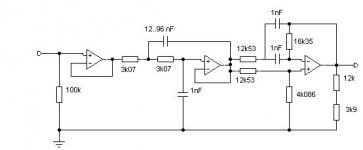
EW/WW Febrary 1995 pp134, 135. Michael Batty - improving Analogue Conversion - getting the best high frequency performance from a clocked DA convertor normally needs a complex post conversion filter designed using cad. This sin(x)/x correction filter provides an easy to implement yet effective means of a compensating for a clocked data convertor's natural roll off.
......Conversion is normally followed by a low pass reconstruction filter. This is typically a high order elliptic design giving a relatively flat response up to just below half the sampling frequency, Fs, followed by a sharp cut-off.
But this arrangement provides no correction for the sinc fall off in amplitude naturally produced by the saple and hold function.
As shown (graph) the roll off reaches -3.9 dB at Fs/2, falling to zero at Fs. Correction for this roll off can be designed into the reconstruction filter if CAD design tools are available, but the simple seperate correction filter described here yields excellent results and allows more flexible design.
The correction filter is a simple second-order low-pass section, with frequency and Q optimised to have a response almost exactly inverse to that of the sinc roll off function up to around 0.4 Fs. If required, a single additional second-order all-pass stage can be cascaded to improve delay equalisation of the correction filter.
Note that in most practical situations, the delay equalisation stage may be omitted, since it is unlikely that the accompanying recostruction filter will itself have linear phase.
Also, the correction filter alone is not useful as a reconstruction filter, due to it's rather poor roll off characteristics.
The low pass stage produces a surprisingly flat equalisation of the sinc function : to within +/- 0.01 dB from 0 to 0.4 Fs, with an error of -0.12 dB at 0.5 Fs.
The optional delay equalisation stage results in an overall phase linearity to within +/- 0.5 * from 0 to 0.4 Fs, or a group delay variation of less than +/- 0.7 % within this range.
Components of 1% tolerance or better should be used.
Circuit Description - Preceded by a unity gain buffer stage to provide low source impedence, the low-pass section uses a standard unity-gain Sallen and Key design. The optional delay EQ section includes a final gain stage to compensate for 12.2 dB loss in the all-pass stage.
Component values in the two filter stages may of course be modified for other values of Fs by scaling either resistor or capacitor values in the standard manner.
Block diagram = DA conversion and reconstruction filter TO Second order LP (F0=0.72 Fs, Q=1.80) TO Second order all-pass (F0=0.556 Fs, Q=0.571)
Eric.
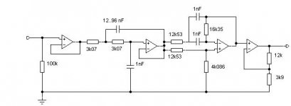
Ok Readers Digest version....
EW/WW Febrary 1995 pp134, 135. Michael Batty - improving Analogue Conversion - getting the best high frequency performance from a clocked DA convertor normally needs a complex post conversion filter designed using cad. This sin(x)/x correction filter provides an easy to implement yet effective means of a compensating for a clocked data convertor's natural roll off.
......Conversion is normally followed by a low pass reconstruction filter. This is typically a high order elliptic design giving a relatively flat response up to just below half the sampling frequency, Fs, followed by a sharp cut-off.
But this arrangement provides no correction for the sinc fall off in amplitude naturally produced by the saple and hold function.
As shown (graph) the roll off reaches -3.9 dB at Fs/2, falling to zero at Fs. Correction for this roll off can be designed into the reconstruction filter if CAD design tools are available, but the simple seperate correction filter described here yields excellent results and allows more flexible design.
The correction filter is a simple second-order low-pass section, with frequency and Q optimised to have a response almost exactly inverse to that of the sinc roll off function up to around 0.4 Fs. If required, a single additional second-order all-pass stage can be cascaded to improve delay equalisation of the correction filter.
Note that in most practical situations, the delay equalisation stage may be omitted, since it is unlikely that the accompanying recostruction filter will itself have linear phase.
Also, the correction filter alone is not useful as a reconstruction filter, due to it's rather poor roll off characteristics.
The low pass stage produces a surprisingly flat equalisation of the sinc function : to within +/- 0.01 dB from 0 to 0.4 Fs, with an error of -0.12 dB at 0.5 Fs.
The optional delay equalisation stage results in an overall phase linearity to within +/- 0.5 * from 0 to 0.4 Fs, or a group delay variation of less than +/- 0.7 % within this range.
Components of 1% tolerance or better should be used.
Circuit Description - Preceded by a unity gain buffer stage to provide low source impedence, the low-pass section uses a standard unity-gain Sallen and Key design. The optional delay EQ section includes a final gain stage to compensate for 12.2 dB loss in the all-pass stage.
Component values in the two filter stages may of course be modified for other values of Fs by scaling either resistor or capacitor values in the standard manner.
Block diagram = DA conversion and reconstruction filter TO Second order LP (F0=0.72 Fs, Q=1.80) TO Second order all-pass (F0=0.556 Fs, Q=0.571)
Eric.
- Status
- This old topic is closed. If you want to reopen this topic, contact a moderator using the "Report Post" button.
- Home
- Source & Line
- Digital Source
- how to design sinx/x filter for TDA1541A?