Can people list their top favourite DAC project (that they have personal experience with) along with rationale as to why they think that particular project is the top-notch (for them).
A rough template:
1) Name of project / DAC (along with version number, if there are several)
2) URL if exists (for more information)
3) Pros and cons (price, sound, easiness of building, pickiness with sources, amount of learning required, etc.)
4) Why it's the best for you (your rationale). Can be sound, can be cost, can be measurements, easiness of obtaining parts or something else. It's what *you* decide. Others don't have to agree, but do give some idea of your personal reasons.
And, PLEASE no fights. If you don't disagree with somebody's personal choice, post your own personal DAC favourite.
My reason for asking this?
There are a ton of of DAC projects out there.
Beginners would probably get a lot of info out of a thread that discussed the pros and cons of several projects and people's opinions of them.
PCM2902 USB DAC/ADC
http://hepso.dna.fi/misc/pcm2902/PCM2902_usb_dac.html
Pros:")
Cheap and parts easy to come by
Reasonably easy to build with not too many parts
Great sound quality (certainly compared to any commercial soundcard)
Upgradeable - has an S/PDIF output which can be passed to a secondary DAC if needed
Works well with a gainclone
Cons:
SSOP PCM2902 chip can be a little tricky to solder though unless you are fairly experienced
I had a few problems getting the device to be recognised by my system though it might be motherboard specific as I had no problems using it in other PC's.
---
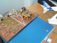
I seriously wanted to upgrade my sound output from my computer having recently built a gainclone (which I *love*) and the existing, noisy, resampling SBLIVE! was no good.
I came across Markku Pöysti's design for this DAC, got some free BB PCM2902 samples from Texas and the rest of the components from Farnell. I etched my own board, soldered it all together and have been very happy.
Attached is a pic of my DAC sitting atop my Gainclone - no box for it yet though
http://hepso.dna.fi/misc/pcm2902/PCM2902_usb_dac.html
Pros:
Cheap and parts easy to come by
Reasonably easy to build with not too many parts
Great sound quality (certainly compared to any commercial soundcard)
Upgradeable - has an S/PDIF output which can be passed to a secondary DAC if needed
Works well with a gainclone
Cons:
SSOP PCM2902 chip can be a little tricky to solder though unless you are fairly experienced
I had a few problems getting the device to be recognised by my system though it might be motherboard specific as I had no problems using it in other PC's.
---
I seriously wanted to upgrade my sound output from my computer having recently built a gainclone (which I *love*) and the existing, noisy, resampling SBLIVE! was no good.
I came across Markku Pöysti's design for this DAC, got some free BB PCM2902 samples from Texas and the rest of the components from Farnell. I etched my own board, soldered it all together and have been very happy.
Attached is a pic of my DAC sitting atop my Gainclone - no box for it yet though
Attachments
halcyon said:
1) Name of project / DAC (along with version number, if there are several)
2) URL if exists (for more information)
3) Pros and cons (price, sound, easiness of building, pickiness with sources, amount of learning required, etc.)
4) Why it's the best for you (your rationale). Can be sound, can be cost, can be measurements, easiness of obtaining parts or something else. It's what *you* decide. Others don't have to agree, but do give some idea of your personal reasons.
Good initiative !
1)
Our DAC page
2)
http://www.tentlabs.com/Products/DIYDAC/DIYDAC.html
3) Pros
Comes with all required schematics, parts list and extensive building manual. Exhaustive background on the design, so much can be learned yet without building. Hard to get parts made availabe at TentLabs. Room for tweaking and component optimalisation.
3) Cons
Not the cheapest one around (700 euro). Requires some experience in soldering (SMD) allthough hundreds are built around the world, all work as required. 3 PCB design, cannot be fit into smal cabinet.
4)
Tradditional design using best chipset of 10 years ago. Very high attenuation to jitter suppression, applied techniques have not been found in other (commercial) designs. Highly insensitive for drive quality.
High attention to PCB layout and signal quality. Tradditional tube output stage and rectifier.
Soundwise it is hard to beat at this price. It offers a high level of detail and transparency.
best
halcyon said:Can people list their top favourite DAC project (that they have personal experience with) along with rationale as to why they think that particular project is the top-notch (for them).
A rough template:
1) Name of project / DAC (along with version number, if there are several)
2) URL if exists (for more information)
3) Pros and cons (price, sound, easiness of building, pickiness with sources, amount of learning required, etc.)
4) Why it's the best for you (your rationale). Can be sound, can be cost, can be measurements, easiness of obtaining parts or something else. It's what *you* decide. Others don't have to agree, but do give some idea of your personal reasons.
And, PLEASE no fights. If you don't disagree with somebody's personal choice, post your own personal DAC favourite.
My reason for asking this?
There are a ton of of DAC projects out there.
Beginners would probably get a lot of info out of a thread that discussed the pros and cons of several projects and people's opinions of them.
1) DDDAC1543
2) www.dddac.de
3) Pro and Con
PRO Highest possible value for money. Beats many other DACs and high priced CD players from the box. Works with parallel DAC chips to overcome some what rough sound if only one chip is used. Asynchrone reclocking with a jitter free TENT Clock for spatial soundstage. Output is passive I/V with high drive capability and direct almost 2 VRMS output without using opamps or tubes. Relatively easy to build, also for beginners (so far everyone 100% get the thing to work...) A starterkit is available for 112 Euro including all parts, except the power supply or battery, cooling and chassis. WEB Site with full description and circuits. Sound is very direct, very pin point and dynamic
CON No state of the art PCB and high end components. For optimium results, need to do some DIY tweaking (but that was actually the idea behind it
 . Sound is for some people not high-end detailed enough. With tweaking on capacitors and using more dacs in parallel this can be pushed in the right direction. The DAC tower gets pretty hot and the kit is not including cooling for the tower, so it needs some creativity to keep the tower cool. I have seen quite some impressive solutions by the way
 4) as said, for those not able and willing to built a largly complicated DAC or lack the budget, should try this design....
doede
www.dddac.de
I concur with Doede. The DDDAC is hard to beat for great sound and simplicity to build. As for cooling the chips, just aim a little muffin fan at the chip tower. Fan can run at 6 volts to be quiet.
The Tent Clock adds to the whole thing.
I built mine using 4 separate battery supplies.
Base drive is wonderful...lots of air and deep soundstage. Details galore.
My other DAC is a Norm Tracy X-DAC signature...Its a great DAC as well, But Its the Doede DDDAC that I keep in my system...It has a warmth and presence that I like.
Fedde Bouwman's NONOZ-III
1) NONOZ-III
2) http://jwg.student.utwente.nl/fedde/nonoz3.html or via http://www.fedde.tk/
3)
Pros: Low cost, good sound, easy to build.
Cons: No PCB-layout (had to do my own), CS8412/8414 difficult to source.
4) I absolutely love this little DAC. Performance is very good (especially for the price) and it's easy to build and so cheap that you can basically fit it anywhere. The board only requires a single supply of 11VDC or more, so stealing the supply voltage for it inside existing equipment shouldn't be a problem in most cases
Pics of my prototype. The PCB is my design and measures app. 63x45 mm
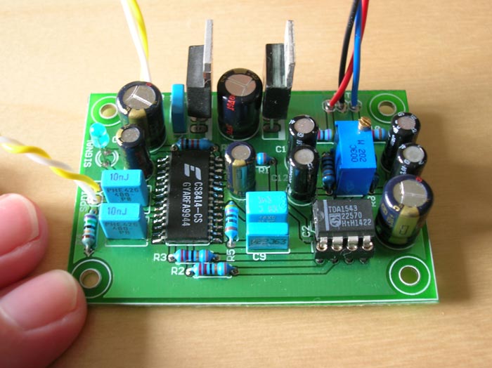
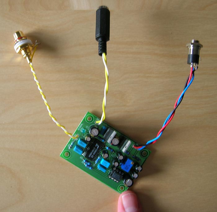
/U.
1) NONOZ-III
2) http://jwg.student.utwente.nl/fedde/nonoz3.html or via http://www.fedde.tk/
3)
Pros: Low cost, good sound, easy to build.
Cons: No PCB-layout (had to do my own), CS8412/8414 difficult to source.
4) I absolutely love this little DAC. Performance is very good (especially for the price) and it's easy to build and so cheap that you can basically fit it anywhere. The board only requires a single supply of 11VDC or more, so stealing the supply voltage for it inside existing equipment shouldn't be a problem in most cases
Pics of my prototype. The PCB is my design and measures app. 63x45 mm
/U.
1) Pedja's TDA1541 dac
2)http://users.verat.net/~pedjarogic/audio/tda1541a_dac/tda1541a_dac_rev.htm
3) Pro's Excellent sound, the optional Reclocker, nice pcb and well laid out
Con's, you need to supply your own components but this is something I would have prefered anyway
I've built a few different TDA1543 and TDA1541 type dacs and this is my favourite so far
Pedja Rogic DAC 1541A.
1. Pros
Natural sound of very high quality. I was able to notice many hours spent on design to get absolute best. Well done Pedja! It serves me as a reference sounding DAC while modifying other digital equipment. Object of desire for many high enders who have ridiculously expensive DAC's. It gives as natural and as unprocessed sound as possible (from a DAC) in it's original form - without reclocker. With reclocker, it is very pleasing but looses just a smallest bit of naturalness. Analog section is ingenious in its implementation. Power supply regulation the best possible.
2. Cons
Parts are obsolete and it would be a good idea to re-design, and implement the widely available receiver and DAC chips.
I played with ground topology a bit and would change couple of things - but that's me!
The reclocker section could be implemented on the same (main) DAC PCB, and have (jumper?) options for a "direct through", or "with the reclocker".
Extreme_Boky
Re: HEREs my version
Any chance we can see a shematic of the 1865/CS8412 setup. Also I like the PCM2902 design, the external supply is an interesting option as it enables batteries instead of using the USB supply. Do you need TTL convertoes on digital ins and outs?
G.
abidr said:Heres my version of DAC using PCM 290x, and another one using CS8412/AD1865 in underway with discrete section of FETs and it really rock. Though protyping on bread board has been done.
Any chance we can see a shematic of the 1865/CS8412 setup. Also I like the PCM2902 design, the external supply is an interesting option as it enables batteries instead of using the USB supply. Do you need TTL convertoes on digital ins and outs?
G.
Evaluation board
Has anyone tried the AD1853 evaluation board sold by ADI?
http://www.analog.com/UploadedFiles/Evaluation_Boards/Tools/73140863EVAL1853EB_a.pdf
The price looks tempting and it seems to be well designed.
The output chips are not so great but could be upgraded to better ones.
Any flaws or problems you can predict on this board?
Carlos
Re: Evaluation board
the usual flaws: analog, like you indicated, and jitter, and decoupling and board layout (ferrite between analog and digital ground because they don't get it right the default way.......)
cheers
carlmart said:
The output chips are not so great but could be upgraded to better ones.
Any flaws or problems you can predict on this board?
Carlos
the usual flaws: analog, like you indicated, and jitter, and decoupling and board layout (ferrite between analog and digital ground because they don't get it right the default way.......)
cheers
Re: Re: Evaluation board
it's even worse, they put a PAL between the IR and the DAC..........
every USD you pay for such a board is too much, better do your own design after carefully reading through DIYaudio
Guido Tent said:
the usual flaws: analog, like you indicated, and jitter, and decoupling and board layout (ferrite between analog and digital ground because they don't get it right the default way.......)
cheers
it's even worse, they put a PAL between the IR and the DAC..........
every USD you pay for such a board is too much, better do your own design after carefully reading through DIYaudio
Re: Re: Re: Evaluation board
OK.
Changing the chips
Improving the clock
Improving the decoupling
Are probably things I can do.
Not so sure how to go about the ground layout and solve its problems.
Yes, I see it. What's that for?
Agreed. Any suggestion? For my application, inside a Pioneer DV525, this DAC doesn't need to be too sophisticated. I2S might be an option, but I am not too sure if I can implement it.
Carlos
Guido Tent said:
the usual flaws: analog, like you indicated, and jitter, and decoupling and board layout (ferrite between analog and digital ground because they don't get it right the default way.......)
OK.
Changing the chips
Improving the clock
Improving the decoupling
Are probably things I can do.
Not so sure how to go about the ground layout and solve its problems.
Guido Tent said:
it's even worse, they put a PAL between the IR and the DAC..........
Yes, I see it. What's that for?
Guido Tent said:
every USD you pay for such a board is too much, better do your own design after carefully reading through DIYaudio
Agreed. Any suggestion? For my application, inside a Pioneer DV525, this DAC doesn't need to be too sophisticated. I2S might be an option, but I am not too sure if I can implement it.
Carlos
I agree with Guido. I used to believe what AD said about grounding. Then we built a D/A box, and they started coming back...................
I learned the hard way. The hard way being buying too many '1862s to replace the ones that died. A good chip, once I stopped them from blowing up.
OK........part of it was my fault. Stiil, ignore everything that they say about grounding, and build your own.
Jocko
I learned the hard way. The hard way being buying too many '1862s to replace the ones that died. A good chip, once I stopped them from blowing up.
OK........part of it was my fault. Stiil, ignore everything that they say about grounding, and build your own.
Jocko
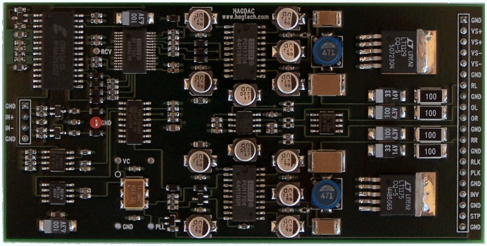
My favorite is the unit that I designed a few years ago which uses a fairly standard chipset in the CS8414, DF1704 and PCM1704, but takes a pretty big turn after that.
The main design goal was to provide sufficient jitter immunity as to make the sound of the DAC independent of the transport and cable. It took some real effort to accomplish, but I think it does provide better jitter immunity than just about any DAC on the market. The measured data correlated jitter on the clock at the actual D/A convertor is more than 1000x less than on the output of the SPDIF receiver, which is near my limit of measurability. The basic methodolgy is to completely isolate the digital input/processing section, with the only clock allowed out an approximately 1 Hz sync pulse used to reconstruct a new DAC conversion clock in a jitter free environment based on the average difference between the input and regenerated clock over that 1 second period. The difference pulse is then spread over the next few seconds via an isolated, integrating PLL operated open collector into a very high quality loop filter to control The precision VCXO. Of course, it required much care in design and layout to realize and maintain the goal.
In addition, it has many other features such as L-C filtering on all the power supplies, no electrolytic capacitors anywhere in the analog stages (only polypropylene and paper dielectric types), and only quality molded tantalums in the digital section. Shunt voltage regulators using isolated lithium battery references control all the power in the analog and clock sections, with the resistance of the 3H chokes forming the regulator series element. All resistors in the analog stages are the excellent sounding (and expensive) precision plastic bobbin-wound coil type, which avoids the ceramic sound of most other types.
I use the DF1704 in the slow rolloff mode, and the current outputs from the PCM1704's go to a simple discrete I/V current mirror stage operating without feedback and providing about a 4 ohm dynamic impedance to the DACs, followed by a cascoded mosfet stage operating single-ended class A with no feedback and about 70mA bias.
I have two separate switched VCXO's in the clock section to allow use with 44.1K, 48K and 96K sources. Selection is automatic based on the frequency sensed and reported by the CS8414. Lots more, but that's some of the highlights. Works very well and sounds great! Only made 5 of them so they're highly collectable
Jocko Homo said:I agree with Guido. I used to believe what AD said about grounding. Then we built a D/A box, and they started coming back...................
I learned the hard way. The hard way being buying too many '1862s to replace the ones that died. A good chip, once I stopped them from blowing up.
OK........part of it was my fault. Stiil, ignore everything that they say about grounding, and build your own.
Building my own with a part that is SSOP-sized and with 28-pins? Certainly not!
But what is that AD say about grounding that should be ignored?
Carlos
carlmart said:
Building my own with a part that is SSOP-sized and with 28-pins? Certainly not!
But what is that AD say about grounding that should be ignored?
Carlos
28 pin SSOP is not so hard to solder, plenty of people are building PCM2902/2906 based USB units with this type of chip. Dont let the pin spacing scare you...honestly it is harder to align the chip to the pads than to solder it.
- Status
- This old topic is closed. If you want to reopen this topic, contact a moderator using the "Report Post" button.
- Home
- Source & Line
- Digital Source
- Your favourite DAC project (post here) ?