the addition of an energy storage element would make the timing of the edge more indeterministic
Absolutely not. No more indeterminate than the straight RC (which already has a storage element). In fact, the removal of noise improves the jitter situation.
You are correct, however, in that the inductance adds a delay, roughly equal to the risetime. That is why you have to do it to all the digital lines, to maintain relational timing.
jh
")
Hi,
So these series resistors before the dac....
I suppose one can only tell what the square waves look like by using the correct equipment, and measuring them since in the models \ datasheets for receivers / filters only perfect squarewaves are produced.
My Philips cd723 has 3 series resistors on the I2S (changed to 20ohm) built into the design.
Kind regards,
Ashley.
ash_dac said:Hi,
So these series resistors before the dac....
I suppose one can only tell what the square waves look like by using the correct equipment, and measuring them since in the models \ datasheets for receivers / filters only perfect squarewaves are produced.
My Philips cd723 has 3 series resistors on the I2S (changed to 20ohm) built into the design.
Kind regards,
Ashley.
This is precisely the kind of topic covered by High Speed Digital Design and there is more on this in the publications section of Howard Johnson's site www.sigcon.com
Re: Re: Discrete DAC
Hi
No need for low inductance, but don't use wirewound, I like carbon types.
Some experimenting is needed on the values, as optimisation of risetime differs from gate bto gate
best
triode_al said:
When I implemented your clock in a Philips player i also added the clock to the controller with a 10 ohm (standard 0,1W mini) resistor. I just did it, thinking it would stop reflections.
I have seen this in Pedja's design (where it is called "optional LPF resistor" without a value; and the DDDAC has 20ohm in the clock to the DAC.
I am curious if this should be a non-inductive (e.g. pressed carbon) type; is 6 - 10 ohms enough? Or does it matter a lot on circumstances?
Hi
No need for low inductance, but don't use wirewound, I like carbon types.
Some experimenting is needed on the values, as optimisation of risetime differs from gate bto gate
best
Re: Re: Re: Your favourite DAC project (post here) ?
Hi
Honestly, this is the first time I hear about this, haven't had feeback from Zeuslab, and if I recall correctly, I never sold that much PCB's to one person.
Nevertheless, if PCB's seem to be faulty, they should be returned to me for inspection.
By the way, they have silver immersion finish now, in order to meet leadfree requirements.
best
Valery said:
Hi, Guido.
I'm going to order your DAC but one question before. A friend of mine from Moscow (ZEUSLAB), who build more than 10 your DAC's with immutable success told me that the quality of Digital PCB ( 4 layer, gold finish) is noticeably fall-off. So was it just some kind of bad batch or whatever?
Thank you,
Valery.
Hi
Honestly, this is the first time I hear about this, haven't had feeback from Zeuslab, and if I recall correctly, I never sold that much PCB's to one person.
Nevertheless, if PCB's seem to be faulty, they should be returned to me for inspection.
By the way, they have silver immersion finish now, in order to meet leadfree requirements.
best
Re: Re: Re: Re: Your favourite DAC project (post here) ?
Thank you, Guido.
Several people bought your KITs & Zeuslab just assemble them, so he didn't ordered so much. Anyway he told me that this DAC is the best he ever heard. O.K. then, I will place my order.
Regards,
Valery.
Guido Tent said:
Honestly, this is the first time I hear about this, haven't had feeback from Zeuslab, and if I recall correctly, I never sold that much PCB's to one person.
Nevertheless, if PCB's seem to be faulty, they should be returned to me for inspection.
By the way, they have silver immersion finish now, in order to meet leadfree requirements.
best
Thank you, Guido.
Several people bought your KITs & Zeuslab just assemble them, so he didn't ordered so much. Anyway he told me that this DAC is the best he ever heard. O.K. then, I will place my order.
Regards,
Valery.
Re: Fedde Bouwman's NONOZ-III
Any chance you can post or even email me the PCB layout for that little DAC board. It's pretty much exactly what I have been looking for. I would like to replicate the design in EAGLE and make some very minor modifications before I etch my own boards.
Thanks.
G.
Nisbeth said:1) NONOZ-III
2) http://jwg.student.utwente.nl/fedde/nonoz3.html or via http://www.fedde.tk/
3)
Pros: Low cost, good sound, easy to build.
Cons: No PCB-layout (had to do my own), CS8412/8414 difficult to source.
4) I absolutely love this little DAC. Performance is very good (especially for the price) and it's easy to build and so cheap that you can basically fit it anywhere. The board only requires a single supply of 11VDC or more, so stealing the supply voltage for it inside existing equipment shouldn't be a problem in most cases
Pics of my prototype. The PCB is my design and measures app. 63x45 mm
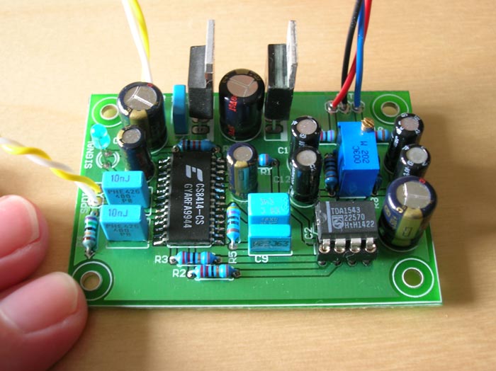
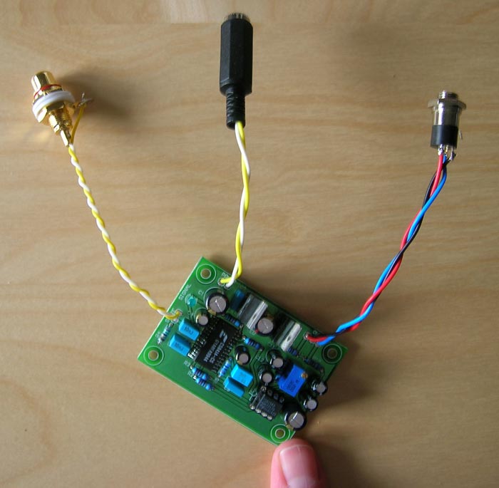
/U.
Any chance you can post or even email me the PCB layout for that little DAC board. It's pretty much exactly what I have been looking for. I would like to replicate the design in EAGLE and make some very minor modifications before I etch my own boards.
Thanks.
G.
 . Does anybody can advise me or give me a circuit ? Thanks forwardly
- Status
- This old topic is closed. If you want to reopen this topic, contact a moderator using the "Report Post" button.
- Home
- Source & Line
- Digital Source
- Your favourite DAC project (post here) ?