So, I hypertuned this player.
Result is an audio beast.
Now I can say that I have a player that really makes music flow, with excellent dynamics, resolution, detail, no harsh ... bla bla bla
I started to modify this player one year ago and after each modification the player was extensively listen by me and a group of audiophile friends.
I didn't manage to get a schematic, but I'll try to share with you modifications I made so far.
Here is a list with my modifications (the moust important ones):
SERVO
=====
- LM324 - motor turntable circuit driver was replaced with OPA404 and decoupled with 2 x 100uF Oscon
- turntable motor control JRC4560 was replaced with AD826 and decoupled with 2 x 270uF Oscon
- 33uF capacitor - part of laser cc - was replaced with 47uF Oscon. This is between TDA5708 pin 17 and ground
- TDA5708 and TDA5709 decoupled with 100uF Oscon
- smd capacitor 470pF HFin TDA5708 pin 3 was replaced with polystyrene 470pF
- smd capacitor 5,6nF LPF TDA5708 pin 14 was replaced with polystyrene 5,6nF
- L272MB replaced with L2722 - radial and focus drive
- there are also few 1mH inductors placed in key posistions (supply rails), but I need schematic in order to give you exact position
DECODER & DAC
============
- non oversampling modifications as described on this forum
- Elso Kwak V7 clock - Thanks Elso for sharing !!!
- SAA7210 decoupled with 100uF Oscon and a small heatsink
- SAA7220 decoupled with ferite bead and 270uF Oscon + 2,2nF polystyrene + small heatsink
- SAA7210 HFi pin 25 - capacitor replaced with 1uF polypropylene
- SAA7210 FB pin 24 - capacitor replaced with 2,2uF polypropylene
- TDA1541 changed with TDA1541A and decoupled with 1mH + 270uF Oscon
- TDA1541A pin 16-17 added capacitor 470pF silver mica
- very important TDA1541A need a small heatsink
- TDA1541A cc decoupling with 14 x 220nF polyestere
OUTPUT
======
- LPF removed, de-emphasis as well
- LM833 changed with AD826ARZ - these are SMD and need very small hetsink
- AD826ARZ decoupled with 470nH inductors and 270uF Oscon
- output capacitors changed to 2 x 270uF Oscon bypassed with 2 x 100nF polypropylene
- mute circuit removed
SUPPLY
======
- +/-15V (7815/7915) moved to main heatsink
- all 1N400x rectifiers changed to BYV27 and BYV32
- all electrolitics replaced with Sanyo 105°C and Oscons after regulators.
Regards, tibi
Thanks Tibi and Hello Everyone!
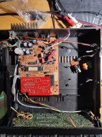
Recently I bought Marantz CD-56, I believe 1st generation as I was curious about the sound of the famous DAC and with the intension to install USB interface and lampization...
So far I find the sound rather dull, there is bass, but not enough, heights are lacking for my test - compared it with FM radio and smartphone output.
It is connected to tube amp without tone stack, but with active 12" (car) subwoofer.
Recap is also planned, but mods will have to wait other priority tasks...
I could manage to find the attached closest service manual - for CD-65. I find some differences, but this is closest possible so far.
Attachments
Listened for a while my CD-56… may be the sound is not too bad.
I’m just comparing the CD-56 with the turntable, which sounds deeper and more “alive” for me… but I have tone stack there with trebles and bass at max.
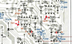
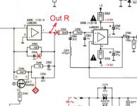
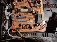
As first mod I used the Lampizator’s “snap” procedure, eliminating the high pass filters and second opamp stage with direct temporary output through 4.4uF WIMA capacitors, until the actual lampization.
Pictures are attached.
Actually, I don’t hear improvement in high tones sound, but the output is only slightly low and again louder than smartphone/FM tuner. Therefore, we really don’t need the 2nd stage and the strange output arrangement after.
I made a video with comparison between it and smartphone/FM tuner after the “snapping”:
Marantz CD-56 vs Sony Xperia vs Pioneer FM Tuner
I’m just comparing the CD-56 with the turntable, which sounds deeper and more “alive” for me… but I have tone stack there with trebles and bass at max.
As first mod I used the Lampizator’s “snap” procedure, eliminating the high pass filters and second opamp stage with direct temporary output through 4.4uF WIMA capacitors, until the actual lampization.
Pictures are attached.
Actually, I don’t hear improvement in high tones sound, but the output is only slightly low and again louder than smartphone/FM tuner. Therefore, we really don’t need the 2nd stage and the strange output arrangement after.
I made a video with comparison between it and smartphone/FM tuner after the “snapping”:
Marantz CD-56 vs Sony Xperia vs Pioneer FM Tuner
Attachments
I noticed strange behavior - as the CD tray drive belt was loosed, but still able to eject/retract the tray - I saw that when tray is ejected, the motor is still running and the shaft is slipping into the belt...
And the motor is still running while the tray is out. I traced what happens - when the tray is fully out, the wheel 104 forces lever 103 to push switch SK12 down and the motor is running.
So switch SK12 is forcing motor to eject the tray out. I my opinion it should stop it.
How are the thing in your players?
I just disconnected the down wire of the SK12 switch and tray motor operates normal.
Several days nothing unusual - tray operates ok and no problems at all.
Unfortunately, the above Marantz CD-65 service manual does not contains the motors drive circuits, but I found Grundig CD8200/CD8400 service manual that is also with CDM-2/10 mechanics. All other circuits (except control board) are very close to the Marantz as it is basically Philips inside.
But it's not clear for me - in the circuit the 2 switches are marked differently (although on the mechanics schematic they are SK1 / SK2):
(p. 17 of grundig cd 8400_8200 schematic.pdf)

But it's not clear for me - in the circuit the 2 switches are marked differently (although on the mechanics schematic they are SK1 / SK2):
(p. 17 of grundig cd 8400_8200 schematic.pdf)
Last edited:
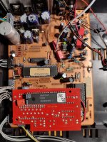
I tried to connect Amanero USB module before SAA7220 with the following scheme:
DATA (R215) pin 3 SAA7220 to DATA Amanero.
CK (R214) pin 2 SAA7220 to BCLK Amarero.
WS (R213) pin 1 SAA7220 to FSLK Amanaro.
I used intermediate 24 pin socked to which I connected the USB module - it could be seen on the clip on the link. (The bottom pins of the intermediate socked were not removed to assure data from Decoder - SAA 7210)
When powered-up the player, it doesn't respond to commands and showed " 0 00.00 " on the display.
I tried to play something form the PC - the USB was recognized as something like USB Amanero Combo 384 Audio - but there was only pink noise afterwards.
I powered-off the player and removed the intermediate socked and plugged back SAA 7220.
When I powered-up and push play - after spinning the disk display shows " 0 00.00 " as there is no disk. Same happens when I eject/load the disc, using the open/close button.
Please see the video on this link:
I tried to bypass the SAA7220 filter with NOS 3x jumper method, the player still doesn't recognize the disk, even worst - the disk keeps spimming.
Please, can someone help me with ideas how to repair my mess, thanks!
Attachments
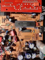
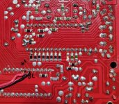
As the USB converter was connected, except to SAA7220, to Decoder SAA7210, I managed to find one...
I swapped the existing decoder - it appeared M4803A under the sticker, but it appears that have the same functions.
No change - after short spinning of the CD, on the display 0 0:00 appeared.
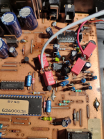
So I checked the solder joints for uP module under the main board and found broken lead on pin 2 - the socked was loose...
I repaired the connection (last pic), but this does not solve the problem.
I swapped the existing decoder - it appeared M4803A under the sticker, but it appears that have the same functions.
No change - after short spinning of the CD, on the display 0 0:00 appeared.
So I checked the solder joints for uP module under the main board and found broken lead on pin 2 - the socked was loose...
I repaired the connection (last pic), but this does not solve the problem.
Attachments
It is strange that during re-cap I have removed at least 3 times the uP module and the CD played fine... and when I tried to connect the USB converter, a broken connection appeared.
I check all pins - there is link between each soldered point of uP socked to its adjacent connection but it still not working...
I will re-solder each of them in case of broken connection below the solder cap.
I check all pins - there is link between each soldered point of uP socked to its adjacent connection but it still not working...
I will re-solder each of them in case of broken connection below the solder cap.
I re-soldered all uP socket pins on the mainboard and also the active pins on the uP board... then powered up the player and no change - after short spin of the CD, 0 0.00 on the display.
Then I decided to swap back M4803A decoder and the payer works.
My guesses are:
1. The broken connection pin 2 interfered the reading from CD and decoder SAA7210P is not compatible - on the service manual is SAA7210 without "P" at the end.
2. There might be other loose connection(s) on the mainboard that suddenly made contact during the last insertion of uP board.
3. I suspect broken cable lead inside its isolation from the 2 interconnecting cable sets between mainboard and the CDM-2/10 mechanism that has connectivity now.
For the record - during the recap of the control board the tray stopped to go out - all cables looked intact on the plug to the board side, but after disconnect, I found broken connection for the motor - there was no resistance between yellow and gray cables, the yellow looks intact, but was broken next to the plug.
Very strange decision single hard leads to be used for the interconnects, maybe cost saving during manufacture... my polish Finesija-3 cassette deck, assembled in Bulgaria in the 80-ties was with all multiwire soft interconnects (most of them with screen).
So interconnects upgrade with soft multiwire is planned.
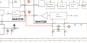
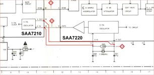
Hi Tibi, is my understanding for bypassing of SAA7220 is correct?Great improvment !
Now SAA7210 feed directly I2S signals to TDA1541A. No more SAA7220 which was completely removed.
The clock is going directly to SAA7210 pin 19 and an extra gate was added across pins 18 and 19.
Now separation between instruments is gorgeous.
tibi
Please chk the attached pic schematic and revert, thanks!
Attachments
No, it not worked...
It must be like this to get rid of SAA7220:
SAA7210 pin 19 must be connected to pin 11 of SAA7220 socked (I actually put bridge between 9 and 11 pins directly in the socked).
SAA7210 pin 18 must be connected to pin 10 of SAA7220 socked - I solder a bridge wire underneath the board.
It must be like this to get rid of SAA7220:
SAA7210 pin 19 must be connected to pin 11 of SAA7220 socked (I actually put bridge between 9 and 11 pins directly in the socked).
SAA7210 pin 18 must be connected to pin 10 of SAA7220 socked - I solder a bridge wire underneath the board.
Attachments
- Home
- Source & Line
- Digital Source
- Marantz CD56 schematic needed