Hi,
Picked up an Arcam Black Box 1.Has anyone modded it?
Inside:-
Twin transformer power supply design
Voltage regulator for each main chip
Back end of a CD player (SAA7220P/A, TDA1541a, custom 'black chip' IC programmed for Arcam)
Class A LF411 dc servo output stage
Tantalum capacitors
IEC mains inlet
Phase switch
Phase-locked loop master oscillator
Sound:- nice sound but treble gritty
Ash.
I had one once..........a "bidnis" contact where you are wanted me to buy some, mod them, and sell them to him. (I won't mention which tube amp company it was...................)
Anyway, it was dreck. One of the worst EMI generators that I have ever brought into my shop. The project was stopped without even trying.
Don't remember a phase-locked master oscillator. I believe that it used a Sony RX chip.
Made for them by TI.
Jocko
Anyway, it was dreck. One of the worst EMI generators that I have ever brought into my shop. The project was stopped without even trying.
Don't remember a phase-locked master oscillator. I believe that it used a Sony RX chip.
Made for them by TI.
Jocko
Firstly I LIKE arcams still have a loved Delta 290 Amp, albeit with it's crappy Pre disabled substituted with a Setpped Attenuator.. Much Better :-0
The Arcan CDP.. which I lusted after for some time.. has fallen far from my wish listr.. replaced by a simple, stupid and disarmingly cheap ($80) Toshiba 3950 DVD player.. Modded to output directly from it's 192 hz 24 bit Burr Brown DAC..
The Arcam is simply outclassed... true.. gotta hear it to believe though :-0.
Suggest you explore this avenue rather than trudging down that dead end road.
Jocko,
I see what you mean about EMI!
My black box is ontop of my amp. I turned the black box on and heard a loud pop from the speakers. Looked at the back of the unit, and to my horror the black box was not even connected to the amp or cd player (interconnects) , it was only plugged into the mains.
Some quotes from the manual:-
"Firstly, it is advisable that your system be switched off before connecting it up to the black box. This will avoid all possible damage to your loudspeakers. At the very least ensure that the volume control on your amplifier is turned down, or an unused input selected." (Arcam blackbox handbook, 1989)
"...all mains powered hi-fi components contain transformers which have a certain stray magnetic field associated with them."(Arcam blackbox handbook, 1989)

Kind regards,
Ashley.
I see what you mean about EMI!
My black box is ontop of my amp. I turned the black box on and heard a loud pop from the speakers. Looked at the back of the unit, and to my horror the black box was not even connected to the amp or cd player (interconnects) , it was only plugged into the mains.
Some quotes from the manual:-
"Firstly, it is advisable that your system be switched off before connecting it up to the black box. This will avoid all possible damage to your loudspeakers. At the very least ensure that the volume control on your amplifier is turned down, or an unused input selected." (Arcam blackbox handbook, 1989)
"...all mains powered hi-fi components contain transformers which have a certain stray magnetic field associated with them."(Arcam blackbox handbook, 1989)
Kind regards,
Ashley.
Fin,
First, I will probably examine what is inside the case, and try to get hold of a service manual.
Second, study the information on super regulators on this forum, and think about how to rebuild the power supply.
Then maybe I should build a digital input board with a CS8412 with I2S straight to the dac section as reversible mod!
Or transplant it somehow into a cdp, and tap I2S direct.
I did notice that there was no mains input capacitor like there is on my Arcam Alpha amp.
Kind regards,
Ashley.
That isn't what I meant by EMI.
Try putting it next to your TV, if you do not have cable/satellite. You'll find out..........very quickly.
Does it use that funky Sony Rx chip???? I sold my last one several years ago, so don't look to me if it is dead. (The DAC-960 used them.....as well as the LHH stuff. I think......)
Jocko
Try putting it next to your TV, if you do not have cable/satellite. You'll find out..........very quickly.
Does it use that funky Sony Rx chip???? I sold my last one several years ago, so don't look to me if it is dead. (The DAC-960 used them.....as well as the LHH stuff. I think......)
Jocko
Hi,
I have now studied the service manual (which is top notch btw).
So far I have changed the dac to TDA1541 s1, and I am pleased with improvement.
Just a few questions about what's in the service manual:-
-TDA1541a has the -5V supply set at -6.2V . The manual does say that the input board and dac need the -6.2V supply. Maybe for convenience use -6.2V ?
Kind regards,
Ashley.
Just asking because current generator supply is between -15 and -5. So 10 volts. If the -15 would be -16.2 to get that 10V, decreasing the -6.2 to -5 would make the 10V 11.6. Which might just be too much again. But n.a. here.
Wonder if decreasing the -6.2 to -5 means a higher current out = louder output
Wonder if decreasing the -6.2 to -5 means a higher current out = louder output
Hi,
Many thanks for the replies.
"The DAC requires 3 supplies to operate correctly, +5V,-6V,-15V" (Black Box Service 1 & 2 D/A Convertor Service Manual, 1991)
The -15V supply is supplied by a 7915 regulator.
The -6.2V supply also supplies the input board. If i'm reading the service manual correctly it's just supplies the NE529 voltage comparator (+5V, and - 6.2V).
In terms of altering the lm337 for -5V supply I used the formula from the datasheet , and calculated that I need to change the R2 resistor to 360. Currently R1=120 ohm, and R2=470 ohm.
Why run at -6.2V when like Ruach says the datasheet shows a -5.5V max?
In terms of EMI reduction I have no info (I would need to read some books!)
Regards,
Ashley.
Many thanks for the replies.
"The DAC requires 3 supplies to operate correctly, +5V,-6V,-15V" (Black Box Service 1 & 2 D/A Convertor Service Manual, 1991)
The -15V supply is supplied by a 7915 regulator.
The -6.2V supply also supplies the input board. If i'm reading the service manual correctly it's just supplies the NE529 voltage comparator (+5V, and - 6.2V).
In terms of altering the lm337 for -5V supply I used the formula from the datasheet , and calculated that I need to change the R2 resistor to 360. Currently R1=120 ohm, and R2=470 ohm.
Why run at -6.2V when like Ruach says the datasheet shows a -5.5V max?
In terms of EMI reduction I have no info
(I would need to read some books!)Regards,
Ashley.
Maybe the comperator needs the -6.2 to work and they did not want to make two supplies. As for the max ratings, maybe the unit started life with the non a version which is -6 (or even -7 according to IEC134).
As for the output current. It is variable in the datasheet:
typical -5 -15 = 10v gives 4 mA so divide 10 by 2500
max -5 and min -15 is -6 and -14 is 8V / 2500 = 3.2
min -5 and max -15 is -4.5 and -16 is 11.5 / 2500 = 4.6
So one should find 3.2 and 4.6 as min and max values.
It actually states 3.4 and 4.6, close enough?
So i still suspect a hight output current if you go for -5.
See what happens.
Hi Guido,
So in the black box: -6.2 -15 = 8.8 divide by 2500 = 3.52ma
So lower output current (good) but the voltage -6.2V is quite high for that pin input(bad). Is this correct ?
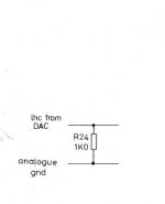
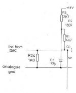
There is a 1K resistor to ground on the dac output listed in the service manual which is confusing me because it seems way too high for tda1541a. Maybe reading the schematic wrong or an error!
Kind regards,
Ashley.
So in the black box: -6.2 -15 = 8.8 divide by 2500 = 3.52ma
So lower output current (good) but the voltage -6.2V is quite high for that pin input(bad). Is this correct ?
There is a 1K resistor to ground on the dac output listed in the service manual which is confusing me because it seems way too high for tda1541a. Maybe reading the schematic wrong or an error!
Kind regards,
Ashley.
Attachments
- Home
- Source & Line
- Digital Source
- Arcam Delta Black Box1 mods