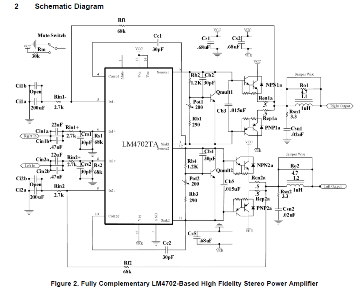
If you want to go with opamps, try this very inventive implementation of the AD844 (common base), which avoids the drawbacks of "standard" opamp I/V's:
http://users.verat.net/~rogic/1541/1541a_rev1_1b_sch.pdf
Read also all explanations on that website. Be aware that you can only use AD844 (and _very_ few others) with such an implementation. Not all current feedback opamps give access to the required circuit nodes.
And you'll need to make some mods, AFAIK PCM63 has not the asymmetric current range as TDA1541.
(I believe the circuit will be simpler in the PCM63 case)
Tino
Re: PCM63K
Probably that sistem work only if two DACs per channel works in balanced mode (on one DAC the signal is phase reversed in digital domain).
Hmm , I can´t find the data about that type of I/V conversion.mpopovics said:Gasho!
I would give a try to Pass D1 output (Pass uses PCM63 too...)
Regards,
Milan
Probably that sistem work only if two DACs per channel works in balanced mode (on one DAC the signal is phase reversed in digital domain).
Gasho,
That switch is the normal /hdcd mode filter. When HDCD is not active, you have to apply 6dB attenuation, which can be done internally in the pmd100, but You loose resolution, or externally in an analogic way, which can be seen on the schematics. [this is the proper, good solution]
By the way, thanks for the schematics!
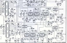
Did You notice the tricky I/V solution applied here by Rotel? I have noticed that when I peeked into my one, and have a certain respect for it. Maybe it would worth a bit deeper digging into..
And, if You decide to go passive, your output resistance is just there, 100 ohm
Ciao, George
A bit more explaining: the "rotel" way of I/V is NOT a proper opamp IV, it is a half way between passive IV / opamp output IV. Tricky.
And I did not change the NE5534 in there, because in that special application is not totally out of place, and maybe - partially - was responsible for the ROTEL's original sound character?
Strange, did You have originally NE5532 -s in place? I have there BB opamps.
The Pass D1 solution is good for single ended, as well.
Ciao, George
I will try with passive , and listen. Gain stage will be made with same OP for unbalanced output , and AD828(double) for balanced output. Between gain stage and I/V stage I will put coupling cap to prevent any DC from I/V to OP-s . In that way I can use smaller capacity and higher grade cap , like AN paper/cooper in oil.
I see in your diagram

that the manufacturer already has nearly a hundred ohm resistance from the PCM63's Iout pin 6 before it gets to a virtual ground. Resistors 301 and 303, and 302 and 304 in the other channel. This tells me that using a resistor for I/V conversion with this DAC chip is valid and should work just fine, with no distortion. Presumidly the designers of that manufacturer had access to more info from BB/TI than just the data sheet. And worked well enough when they did pre production testing. The caps 301, 303, 302 and 304 would act to divert ultrasonic currents to ground. Acting as low pass filters.
Thus you could use a hundred ohm resistor to ground for the I/V conversion, and then feed the resulting voltage into your favorite pre-amp circuit, be it transistor, op-amp, or tube to get it up to line level to feed to your audio amp.
Gasho said:Yes , but for passive I/V conversion , pin 6 on DAC chip must be grounded also.
Not a good idea.
Ok, than connected od pin 6.
Could you explain a little more, I'm not getting your thought that well on this.
I am planning my own DAC, based on CS8412, PMD100 and TDA1541A and a PCL82 outputstage.
Actually I am thinking about the I/V conversion and the Rotel schematics seems to be very interesting, in the matter of the conversion AND the gain switching between CD- and HDCD mode.
I can recognize the I/V conversion in this schematics, built by R301/303 (Left channel). Together with C301/303 they form a LPF, imho.
But, I need some help, to completely understand the feedback path:
What is the gain, applied to the NE5534?
In HDCD-mode, the feedback path is quite simple: R321 1.3K in series with R307 3.3K, resulting in a gain of 47 in relation to the input-R.
But, what happens in CD mode? The feedback path is more than 1Meg in this case???
And what is the reason for C's in the feedback path in CD-mode of this opamp?
Every explanation is welcome!
Franz
P.S.
I plan to use OPA627 for this circuit.
- Status
- This old topic is closed. If you want to reopen this topic, contact a moderator using the "Report Post" button.
- Home
- Source & Line
- Digital Source
- What is better sounding I/V con. ?
