Hi,
Does anyone know what Mission did (if anything to the cd650) to make this player?
CD650:- http://www.diyaudio.com/forums/show...18853&perpage=10&highlight=cd650&pagenumber=3
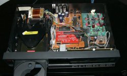
Mission:- see attached pic
(they both have a rear toaster)
Kind regards,
Ashley.
Does anyone know what Mission did (if anything to the cd650) to make this player?
CD650:- http://www.diyaudio.com/forums/show...18853&perpage=10&highlight=cd650&pagenumber=3
Mission:- see attached pic
(they both have a rear toaster)
Kind regards,
Ashley.
Attachments
Hi,
Think it is obvious from the pictures.
The mission has a new output stage. seems they did not mount the standard output circuits on the main pcb (the 650 has two outputs, one on the main and one 'additionally filtered' on the separate pcb on the right.
As for the other changes:
the pcb above the main pcb in the mission contains the decoder microprocessor and some additional logic. This is a bugfix which can also be found in the 650 (mine had one, replaced it with the single microprocessor because the old broke).
the small pcb in the front on the right in the mission is most probably the powersupply for the display. It is integrated on the filter pcb in the 650. Ive done the same in my 650: removed the filter pcb and put a small pcb in for the display powersupply.
The 650 in the picture is modified btw, the caps on the mainboard are like the mission.
Interesting, what chips are on the mission pcb?
http://www.diyaudio.com/forums/attachment.php?postid=220436&stamp=1060669577
Hi,
Thanks for the information.
The chips on the board are:-
4 X hef4051bp
4 X ne5532 signetics
1 X hef4094
hef4094 : 8-stage shift-and-store bus register?
hef4051: 8-channel analogue multiplexer/demultiplexer
Ne5532 (op amp)
I assume most of the chips relate to the display features since some connectors run to the display board, and volume functions (which I cannot access because i'm using a Marantz remote). The player does not work with the extra pcb disconnected.
The player uses the motorola controller rather than a SAA7210. What does the 'bugfix' pcb do ?
In the Mission the Saa7220/A, and TDA1541 were originally inside but i took the TDA1541 out and put in a tda1541A S1 since they had already provided sockets.
Did you add a low jitter clock to your CD650?
Kind regards,
Ashley.
Hi,
The cmos chips will be there for the volumecontrol and maybe even deemphasis switching (i guess).
The smallest pcb is the display powersupply (ac) and +32V for the display driver/keyboard decoder chip. Which communicates with the other controllers (two more iirc).
Yeah, mine also has no 7210 but a M4... something. Never got more info on it. No datasheet But it seems to be pincompatible.
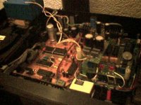
I'm (ab)using my 650 as testmachine. Busy with a dac (2 times 1541, D1 output stage) which also has it's own clock (Tent). See the pic. But currently working on the preamp, pcb on it's way..
Dont really get the fascination for the 650, it's plastic all over... When the dac is finished it's going into a CD80
 ")
Edit: can only guess why they had to add some hardware last minute. Just know the newer versions of the 650 dont have it, there is a single processor used. Got one of them because i killed the processor in my machine and it is pincompatible with the pcb.
The cmos chips will be there for the volumecontrol and maybe even deemphasis switching (i guess).
The smallest pcb is the display powersupply (ac) and +32V for the display driver/keyboard decoder chip. Which communicates with the other controllers (two more iirc).
Yeah, mine also has no 7210 but a M4... something. Never got more info on it. No datasheet
But it seems to be pincompatible.I'm (ab)using my 650 as testmachine. Busy with a dac (2 times 1541, D1 output stage) which also has it's own clock (Tent). See the pic. But currently working on the preamp, pcb on it's way..
Dont really get the fascination for the 650, it's plastic all over... When the dac is finished
it's going into a CD80 Edit: can only guess why they had to add some hardware last minute. Just know the newer versions of the 650 dont have it, there is a single processor used. Got one of them because i killed the processor in my machine and it is pincompatible with the pcb.
The HFE chips I am sure do volume on the mission PCB. What does perplex me is that the audio out from the main PCB goes to the mission PCB as well. Perhaps it just loops to their headphone out but that is volume controilled 2........
BTW, my wife likes this player (though I use a Theta mostly) for its large readable display and I like the fact you can switch off the display. I hjave no original remote either but the standby button on an arcam remote switches off the display.
The mission after better diodes and 627/637 and 2604 sounds really nice and is not a huge step back from the Theta drive and DAC I use. Did no cap upgrades, just put new fresh lytics in most places and a separate reg for the SAA7220 and one oscon on its 5 V supply.
A nice machine. Majke sure the RCA with the resistor is plugged into digital out. Makes a big difference......
G
I got a CD650 today, did not try it up to now but opened it.
The enclosure is a bad and weak plastic thing, it does not convice me.
But the separate audio board calls to be replaced by a tube circuit
I like this flip top transports from Philips. Overall impression about the 650: a nice base for tweaking, I think.
Two questions:
- I dont have the terminator plug for the digital out RCA. What is the resistor in the original? 75 Ohm?
- A service manual available?
Kind regards
Franz
/Edit: I've just seen, that Elso Kwak offered some schematics in another thread. I've sent him a mail, to ask for the manual.
Hi, some thoughts: yes, **** plastic. The separate pcb contains the displaycontroller's powersupply. You need to put that on a separate (small) pcb. look at the link in post 4, the small pcb is high up in the back.
transport is cdm2, works fine since '89.
yes, 75 ohm
got the manual, but only on paper. And it's in dutch..
But i also have the schematics zipped.
mmm, who is putting in the ****
I mean c-r-a-p
transport is cdm2, works fine since '89.
yes, 75 ohm
got the manual, but only on paper. And it's in dutch..
But i also have the schematics zipped.
mmm, who is putting in the ****
I mean c-r-a-p
Hi Guido
No problem: I can read dutch!
I spent many weeks in Netherlands, in the 80ies, working for DEC, Digital Equipment Corp.
This time, I read every day dutch newspapers. But I dont try to speak it, I will never be understood
In the meantime, I got the schematics for the CD650.
Many thanks!
Franz
No problem: I can read dutch!
I spent many weeks in Netherlands, in the 80ies, working for DEC, Digital Equipment Corp.
This time, I read every day dutch newspapers. But I dont try to speak it, I will never be understood
In the meantime, I got the schematics for the CD650.
Many thanks!
Franz
It's mine
Right.
It's much much more modified by now.
guido said:The 650 in the picture is modified btw, the caps on the mainboard are like the mission.
Right.
It's much much more modified by now.

Franz G said:Hi Guido
No problem: I can read dutch!
I spent many weeks in Netherlands, in the 80ies, working for DEC, Digital Equipment Corp.
This time, I read every day dutch newspapers. But I dont try to speak it, I will never be understood
In the meantime, I got the schematics for the CD650.
Many thanks!
Franz
Than there is one problem left, only have a paper copy.
We still use DEC at work, now Compaq, eh HP....
Stuff that keeps on working. Still use EVE now and then to edit a really really huge file with DCL (hope i still have the names right).
Other systems at work (i know of) cant cope
Dont tell anyone, it is one of our core servers Am i getting of track, WELL NO! Got one of the first (DEC) CDROM players, philips stuff inside. Including the CDM3, see the avatar
Guido
Re: Re: It's mine
PMD100 (with digital 6db attenuation disabled) + AD1862 + AD847 I/V + direct output.
guido said:And the winner is .........
PMD100 (with digital 6db attenuation disabled) + AD1862 + AD847 I/V + direct output.
PCM7000 Help
Hi all, i have a PCM7000 with a problem... it starts and plays ok for a bit then the disk just takes off and runs at full speed.
If anyone has any ideas please email me:
lowie@orrcom.co.nz
Thanks
Hi all, i have a PCM7000 with a problem... it starts and plays ok for a bit then the disk just takes off and runs at full speed.
If anyone has any ideas please email me:
lowie@orrcom.co.nz
Thanks
Sounds like a clock issue and it is not something specific to the PCM7000. It can happen to any CD player - so don't just search for your particular model. I've read a few discussions here about this problem but can't find them at the moment. Do some searches for the problem (not the CD player) and you'll find some solutions. Good luck.
Fin said:Sounds like a clock issue and it is not something specific to the PCM7000. It can happen to any CD player - so don't just search for your particular model. I've read a few discussions here about this problem but can't find them at the moment. Do some searches for the problem (not the CD player) and you'll find some solutions. Good luck.
Yeah sounds like the warp speed / centrifuge issue!
Symptoms of a disconnected clock or saa7220 not receieving power.
How did the failure occure ? (was it working before it was modded or did it fail on it's own)
tubenut said:BTW, my wife likes this player (though I use a Theta mostly) for its large readable display and I like the fact you can switch off the display. I hjave no original remote either but the standby button on an arcam remote switches off the display.G
Hey Tubenut
This makes it 2 CD Players that we have in common.....well, almost......the pcm7000 and the arcam delta 70.2/3.
ash_dac said:
In the Mission the Saa7220/A, and TDA1541 were originally inside but i took the TDA1541 out and put in a tda1541A S1 since they had already provided sockets.
Ashley.
Interesting.....mine came with an TDA1541A S1 chip as standard.
tubenut said:BTW, my wife likes this player (though I use a Theta mostly) for its large readable display and I like the fact you can switch off the display. I hjave no original remote either but the standby button on an arcam remote switches off the display.G
Hey Tubenut
This makes it 2 CD Players that we have in common.....well, almost......the pcm7000 and the arcam delta 70.2/3.
Please, can anyone tell me what Philips model (or other model) the Mission PCM II was based on? I've searched and searched on the internet without success. One item I found suggested it was based on the Philips CD650 but according to this thread, that's wrong, it was the Mission PCM 7000 that was based on the CD 650. I believe the PCM II is significantly different from the PCM 7000 - eg it has the CDM4 and the TDA1541A, apparently.
I would greatly appreciate any information you can give me about the PCM II. I recently bought one on an impulse from Ebay and I really like it, but I wish I could find out more about it to decide whether it's worth modding.
Btw, I have just purchased an electronic download of the full CD650 service manual including schematics and when my download arrives, I will be happy to forward a copy to anyone who wants one if it's not copy protected.
- Status
- This old topic is closed. If you want to reopen this topic, contact a moderator using the "Report Post" button.
- Home
- Source & Line
- Digital Source
- Philips cd650, Mission PCM7000 differences ?