Re: a non os dac, but with digital filter?
Not so.
ray.
tbla said:..............if there is a digital filter.....there is oversampling...!
Not so.
ray.

I had a chance to compare TDA1541 and TDA1543 chips. The comparison was not fare, because 1541 chip was used in a Marantz CD94 player and 1543 was an outboard DAC. The output from 1541 went through OPA627 and 1543 was using just the passive stage with 1K resistors so the output was lower. But 1543 used reclocking (100Meg crystal all 3 lines reclocked), the other no reclocking.
I liked Marantz very much and the bass was the most impressive I ever heard from a CD source yet. TDA1543 was also good sounding, but overall, I preferred one box player. I think that when implemented properly, bot chips can be satisfying, both in bass area and resolution. I had a feeling that TDA1541 might be a bit more alive sounding, but again it was hard to get proper conclusion because of different setups.
I liked Marantz very much and the bass was the most impressive I ever heard from a CD source yet. TDA1543 was also good sounding, but overall, I preferred one box player. I think that when implemented properly, bot chips can be satisfying, both in bass area and resolution. I had a feeling that TDA1541 might be a bit more alive sounding, but again it was hard to get proper conclusion because of different setups.
Peter Daniel said:You probably know my all out Broadhurst DAC? The TDA1543 sounded similar and modified Marantz CD-94 was better as a stand alone unit, than as a transport feeding PCM DAC. It was a big eye opener. I hope Jocko reads that")
I don't know the Broadhurst
I saw pictures you posted here, of a dac based on paralleled PCM1704
PS: what dac is built in the cd pro2?
AD1865N-K
Hi Peter,
Audionote is using the much less good AD1865N-J in there DAC1.2 and CD2 CD-player. I am not sure about the top the line DAC5. The picture on there website was too low resolution to decipher the type assignation. The specslist only mentions "AD1865".
http://www.audionote.co.uk
Peter Daniel said:I don't remember, I took it off the board. There is still one chip I want to try: AD1865K. I know that Audio Note is using them and I got at least 6 of them
Hi Peter,
Audionote is using the much less good AD1865N-J in there DAC1.2 and CD2 CD-player. I am not sure about the top the line DAC5. The picture on there website was too low resolution to decipher the type assignation. The specslist only mentions "AD1865".
http://www.audionote.co.uk
Peter Daniel said:You probably know my all out Broadhurst DAC? The TDA1543 sounded similar and modified Marantz CD-94 was better as a stand alone unit, than as a transport feeding PCM DAC. It was a big eye opener. I hope Jocko reads that
Hi Peter,
WRT Broadhurst DAC, does it have CS8420 SRC chip and
which DF does it use. Is there any jitter reduction.
Terry
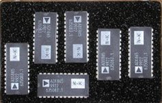
If you look here: http://www.jcaudio.com/product/AudioNote/daccomparison.html
They use the same board for digital section in almost all their DACs, with small differences in components. Comparing it to this pic, you could see they are the same chips.
They use the same board for digital section in almost all their DACs, with small differences in components. Comparing it to this pic, you could see they are the same chips.
Attachments
Peter,Peter Daniel said:I don't remember, I took it off the board. There is still one chip I want to try: AD1865K. I know that Audio Note is using them and I got at least 6 of them
there is an Akai Carousel type multi-disc player that uses the AD1865N DAC.
Every one that goes over my bench has a notably unusually good sound.
Eric.
AD1865N-K
Hi Peter,
As I have the schematics of the Audionote DAC 1.1. & 1.2 where he AD1865N is mentioned. This week I had a look into the Audionote CD-2 at another dealer in town. It had the AD186N-J. I offered the man some AD1865N-K . He was highly interested when I told this was a meaningfull upgrade. AD1865N-J and AD1865N-K picture looks very much the same except the letter J or K. I could not determine if the Audionote DAC5 uses the K or J-version. The link you provided shows the N-version for the 1.1 and 3.1 DAC. Model 4.1 and 5 seem to have a "selected" version of the AD1865. Very probably this is the K-version you have a handfull of. Thanks for the link, very informative!
Peter Daniel said:If you look here: http://www.jcaudio.com/product/AudioNote/daccomparison.html
They use the same board for digital section in almost all their DACs, with small differences in components. Comparing it to this pic, you could see they are the same chips.
Hi Peter,
As I have the schematics of the Audionote DAC 1.1. & 1.2 where he AD1865N is mentioned. This week I had a look into the Audionote CD-2 at another dealer in town. It had the AD186N-J. I offered the man some AD1865N-K . He was highly interested when I told this was a meaningfull upgrade. AD1865N-J and AD1865N-K picture looks very much the same except the letter J or K. I could not determine if the Audionote DAC5 uses the K or J-version. The link you provided shows the N-version for the 1.1 and 3.1 DAC. Model 4.1 and 5 seem to have a "selected" version of the AD1865. Very probably this is the K-version you have a handfull of. Thanks for the link, very informative!
Ad1865n-k
Hi Peter,
I got this picture in my mailbox, which I believe is of a DAC5.
On higher resolution, for this forum it is resized/resampled, it shows clearly that it is a AD1865N.
Apparently Peter Qvortrup didn't find is necessary to use a higher grade version. I think he is wrong.
Anyway owners of Audionote DACs can upgrade there unit simply by replacing the DAC.
Attachments
Peter Daniel said:It uses Cs8420 rev D chip and PDF1704 filter. It operates in asynchronous clock mode (or something like that) for less jitter. By that I mean, that there is a clock onboard.
Hi Peter,
CS8420 is probably weak link in that DAC and may determine
ultimate performance limit. The newer AD1896 ASRC supposedly
sounds much better and measures much better. There are
also newer ASRC chips being developed that will surpass
AD1896.
Hopefully they will get to the point where SPDIF induced jitter
is a moot point, but the digital brick wall filter will always
remain.
Terry
Terry Demol said:
Hi Peter,
CS8420 is probably weak link in that DAC and may determine
ultimate performance limit. The newer AD1896 ASRC supposedly
sounds much better and measures much better. There are
also newer ASRC chips being developed that will surpass
AD1896.
Hopefully they will get to the point where SPDIF induced jitter
is a moot point, but the digital brick wall filter will always
remain.
Terry
Hi Terry
Spot on !
regards
Koinichiwa,
Okay, let's do this one more time. This is actually quite clear from the datasheet if you ask me.
I have already run through this on the gainclone Board, but the search engine there sucks, so I'll run this again. Someone check if I get the same numbers twice... ;-)
Anyway, our absolute, maximum output swing is 1.8V to +V -1.2V. So for 5V this is 5V -1.2V -1.8V = 2V.
The DAC's output full scale current is rated as 2.3mA typhcial, +/-0.35mA. If we assume for a moment the typhical TDA1543 we have 2V peak-peak permissable Voltage swing and 2.3mA peak-peak current swing.
The I/V resistor hence becomes 2V/2.3mA = 869 Ohm. NPV is 910 Ohm, Kusonoki San obviously got away using 1k.
Now the next step. Our "midpoint" voltage must be 1.8V+swing/2 and thus 1.8V+2V/2V =2.8V.
This means we need to have the output produce a current giving 2.8V across a 910 Ohm resistor for digital silence or 1.15mA output current. So the total current must be 3.07mA of which 1.15mA are supplied by the DAC.
Looking at page 5 of the TDA1543 Datasheet we see the DAC output composed out of a variable current sink (the actual DAC) and a fixed current source (controlled by Rref).
Now Vref is fixed at nominal 2.2V and the "gain" for the reference current drawn out of the Vref pin is nominally 2.
As our DAC sinks 1.15mA and 3.07mA are delivered to our external I/V resistor to set the midpoint we need to make 1.15mA+3.07 = 4.22mA flow through our current source and thus 4.22mA/2 = 2.11mA through the resistor from Vref to ground.
With 2.2V reference Voltage and 2.11mA current the Rref resistor should be 1.04k, 1k NPV.
If we want to maximise the DAC's dynamic range, we can ramp up the Supply Voltage to 8V. According to the Datasheet this fully permissable as typhical operation. The ABSOLUTE MAX supply Voltage rating is 9V.
So lets assume we are like Austin Powers and "like to live dangerous". This means we set +V at 8.6V by using a 7808 and a diode.
Our output Voltage swing can now be 1.8V to 8.6V - 1.2V = 7.4V or 5.6V peak-peak (2V RMS). Our full scale current is still only 2.3mA, so our I/V resistors become 5.6V/2.3mA=2.43k NPV = 2k4.
To get the output to the new midpoint of 1.8V+(5.6V/2) = 4.6V. We will have to have 4.6V/2k4 = 1.92mA flowing in our 2k4 resistor, plus our 1.15mA DAC digital silence current, so 3.07mA. In our reference resistor 3.07mA/2 = 1.535mA need to flow, so 2.2V/1.535mA=1.43k, NPV 1k5.
This will of course totally max out the output voltage range and I would suspect that given the permissable tolerance in series production of the chip you would have to select the chips, maybe 1 out of 10 will make the grade.
Does that clear up any remaning certainties?
Sayonara
PS, Kusonokis first DAC used 4 Chips in Parallel, 9V Supply and 620 Ohm IV, plus 390 Ohm Rref. Scaled to signle chip this would be using NPV E12 Resistors the same values I calculated above and is for the I/V resistor consistent with Stereophiles measurements on the Progression DAC....
Thanks for the great explanation !
Just a question or two... could we assume that full scale current is going to be ~2.65mA @ 8.6V. (there is a min and max value for "full scale current" in the data sheet, can we assume this depends on Vdd ?)
Like...asking questions 15 years after the post
- Status
- This old topic is closed. If you want to reopen this topic, contact a moderator using the "Report Post" button.
- Home
- Source & Line
- Digital Source
- Non Oversampling DAC-complementing CD-PRO