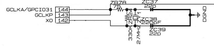
Ok, Ive got this 75% figured out. Im installing a 27mhz tent clock in my HD841. With Guidos help I have figured most of this out. His clock has three outputs, 2 of which are going to be used to bypass a gate circuit. The third is for the input of the main decoder chip which is the image attached. Can someone tell me which is the input of the decoder? I replaced the 22pf caps with 10k resistors and measured ~0v on pins 143/144 and 3.3v on pin 142. I think this means 143/144 are the inputs, but would like someone who knows to back that up.
Attachments
- Status
- This old topic is closed. If you want to reopen this topic, contact a moderator using the "Report Post" button.