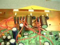
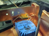
rowemeister said:Anybody who wants to do the reg upgrade, look at this and see how easy it is. I have used LM1084 which are lower noise than 7805.
It will be sold soon
Hi Brent,
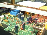
Nice photo's, good job. That reg PCB looks very neat. I was just looking into some regulator data, cause i'll be doing some separate regs too in a while. Still haven't decided on what regs to use.
Isn't the noise for these regulators (LM/LT1084...86, LM317) a typical 0,003% of Vout? That means 150uV at 5V out, while a standard 7805 does 40uV.
Regards,
Ray.
6h5c said:
Hi Brent,
Nice photo's, good job. That reg PCB looks very neat. I was just looking into some regulator data, cause i'll be doing some separate regs too in a while. Still haven't decided on what regs to use.
Isn't the noise for these regulators (LM/LT1084...86, LM317) a typical 0,003% of Vout? That means 150uV at 5V out, while a standard 7805 does 40uV.
Regards,
Ray.
Off the top of my head im not sure. I used 7805 for my servo reg pcb on my uber player and found the 1084/86 adj gave me better bass and a slightly better bass.
I also have some plastic caps to fit across the caps after the regs.
Brent
rowemeister said:Off the top of my head im not sure. I used 7805 for my servo reg pcb on my uber player and found the 1084/86 adj gave me better bass and a slightly better bass.
I also have some plastic caps to fit across the caps after the regs.
Brent
Hi Brent,
I'll look into the datasheets a bit more. Noise spec's aren't everything. Maybe output impedance or ripple rejection has something to do with it. But i've heard it before, that low-drop reg's sound better.
I'll keep it in mind
.Regards,
Ray.
Gooch said:Hi all
Hope this isn't a stupid question. I am getting ready to order the brownbog pcb's for single to dual using OPA627&OPA132. Here is my question do you use 2 opamps pre pcb? Because the OPA2604 are dual opamps the ones that are in there now.
Regards
Dave
Hi Dave,
There's no such thing as a stupid question, unless you know the answer already
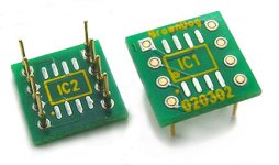
.The two opamps in the player are dual opamps, with two identical opamps in one 8 pin housing. So actually there's four of them. Q605 is used for the left channel, and Q606 for the right. The first half of each chip (pins 1, 2 and 3) is used after the DAC, and the second half (pins 5, 6 and 7) is in the analog filter. With dual opamps you always end up with the same opamp in both places, and that's not optimal. But the adapter enables you to use two different single opamps in a dual socket on the PCB.
To use OPA627 after the DAC and OPA132 in the analog filter, is a nice combination. For each channel you need an OPA627 and an OPA132 (both SMD of course), and a BD adapter. Place the OPA627 in the position of IC1 (on top) of the adapter. Place the OPA132 in the position of IC2 (bottom) of the adapter, that's it. Look at the dot for the pin 1 mark, and make sure you place them the right way around. So each adapter indeed holds two different single opamps.
Regards,
Ray.
Attachments
Gooch said:Hi everyone
I need some help I bypassed the HDAM on Monday and been listening to it all week.Well today someting weird started to happen CD plays to track 3 then stops thing.
Sounds like the flat cable going to the transport, J103
put slight pressure ontop of cable and play something.
allan
Gooch said:Hi Allen
I did that and it didn't help. I wounder if the lazier went out of focus for some reason
Regards
Dave
My cdp played for 2 or three tracks then just stopped.
i had meters and scope on everything trying to find why
thought it was my clock upgrade (loosing sink) or the clocks psu but no.
cleaned laser (dry cotton bud)
replug the cable a few times it played for 4 to 5 tracks
I was starting to think of laser problems too
but
tried moving (bending) cable when playing, no success.
finally put a kink in the cable
no more problem
allan
ps someone mentioned a cap on the transport pcb that dry's out
and gives similar problem to weak laser.
Still trying to fix my display again (which broke not for the first time, lol!)
D852 seemed suspicious so I replaced it with a wire jumper, still not working.
I checked the joints around C854, D851, Q851, C852, D852, C853 and all seems fine.
The front panel receives its +5v (problem last time), this time it's the -24vdc. (should be lower, ~-18v now I replaced D852 with wire.)
If anyone would like to suggest what to do I'd be grateful. I didn't want to ask for help again but I'm a bit stuck now.
The 3.6vac between orange and brown wires measure ok.
The -19.5v isn't right. I'm confused and I don't understand this complex psu arrangement.
The problem is around the 7918 regulator (Q851), it measures:
pin1 - 0
pin2 - -36
pin3 - -26
I don't think this is at all correct, lol!
- Home
- Source & Line
- Digital Source
- Marantz CD63 & CD67 mods list