6h5c said:
Hi Phil!
Doesn't work?? How's that possible? Did you screw it up
?
For now, I use the on-board regulators for the discrete stage, which are LM317/337 BTW. Then the series inductors (220uH) and four Elna Silmics that I stole from the output caps. Sounds quite nice for a prototype.
In the definitive version I want to use Black Gates, and maybe a differential FET input stage. When my FET's arrive i'm going to start testing that.
My new CD57 arrived yesterday
Another virgin PCB waiting to be mounted....
Regards,
Ray.
Ray are you trying to get this site shut down with your virgin pic. lol
6h5c said:
Hey, what can I say, i'm not into opamps anymore anyway....
Ray.
Fair enough
Brent
Doesn't work?? How's that possible ? Did you screw it up ?
No, don't panic. I haven't built it yet. I'm implying it won't work because its my design based on your tube version.
I designed it before you published your transistor version.
Its very similar though. A slightly different current source (using two bipolars), 6kohm collector resistors, and I designed it without a buffer, but will put one in - a series feedback pair with a current source (another one, I like current sources
).I'm just so slow off the starting blocks. I haven't built it yet.
Cheers,
Phil
Ray are you trying to get this site shut down with your virgin pic. lol
LOL!! Ray, you should be more careful.
6h5c said:
Another virgin PCB waiting to be mounted....
 ??!!?? Really Rowe !! Who has the mind of a sewer then ???
Ray : What's going on this board??
rowemeister said:Ray are you trying to get this site shut down with your virgin pic. lol
Brent
philpoole said:LOL!! Ray, you should be more careful.
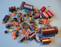
Hey, I was thinking about posting an even more explicit one.
But I have another one that shows some loose parts
Ray.
Attachments
philpoole said:No, don't panic. I haven't built it yet. I'm implying it won't work because its my design based on your tube version.
I designed it before you published your transistor version.
Its very similar though. A slightly different current source (using two bipolars), 6kohm collector resistors, and I designed it without a buffer, but will put one in - a series feedback pair with a current source (another one, I like current sources
I'm just so slow off the starting blocks. I haven't built it yet.
Cheers,
Phil
Hi Phil,
Yeah, well, there's not much to say about a differential stage that's a bit different. It will work fine if you don't use too much soldering poo, like some of us tend to
.Current sink like this? I use it in my tubeamp, works very good. Nice and simple. I feed it off the +350V rail with a 470k resistor, and I've added a 22n cap from the BC547's collector to GND, to get rid of any noise coming through.
Ray.
Attachments
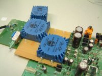
poynton said:Ray : What's going on this board??
That would be the passive filter with tubestage, since the other CD57 holds the transistor stage. I'm swapping parts right now, and it will make a nice comparison when they are both finished. Then i'm going to decide which stage is going to be fitted in my "real" (CD67OSE) player. That one still has the opamp filter.
Griffymark said:This is one hell of a thread and I admit I have not followed the whole thing through ;-> .....but what is the conclusion of the best bangs-for-bucks (and for electrical novices!) mods for these players?
Cheers.
Hi Griffy!
Glad you like the thread. I hate to be boring, but if you start from post #1 you'll get the answer to your question (and lot's more)
. I'm afraid you are not the first to ask this....
Ray.
Hi Ray,
That's the one! I like it because its easy to calculate the resistance required, and I 've used it before with good results. I tend to use BC182s (I tend to work at +/- 15V and they seem to work well).
One day, might look into cascoding and stuff, but I've never really measured performance, so maybe its fruitless until I understand the performance improvements?
Anyway, I built it last night on strip board. Now, my 4.7nF caps are relaltively big polyesters (Brent, its okay, I'll replace with silver mica when I'm happy with it ), and I wasn't trying to save much space, but its actually a big circuit board! I'm a bit worried about how it will fit. If I'm really pleased with it, I might rebuild it. It only took a couple of hours.
I did omit the buffer output, because, to start with, I'll be feeding my headphone amp - whose first stage is a buffer just like this (I was saving time there as I'd realised how big it was getting.
Anyway, its built, plugged it into a PSU and the voltages look good. Hopefully I'll attach it to the CD63 sometime in the next few days. Can't wait.
Cheers,
Phil
Current sink like this?
That's the one! I like it because its easy to calculate the resistance required, and I 've used it before with good results. I tend to use BC182s (I tend to work at +/- 15V and they seem to work well).
One day, might look into cascoding and stuff, but I've never really measured performance, so maybe its fruitless until I understand the performance improvements?
Anyway, I built it last night on strip board. Now, my 4.7nF caps are relaltively big polyesters (Brent, its okay, I'll replace with silver mica when I'm happy with it
), and I wasn't trying to save much space, but its actually a big circuit board! I'm a bit worried about how it will fit. If I'm really pleased with it, I might rebuild it. It only took a couple of hours.I did omit the buffer output, because, to start with, I'll be feeding my headphone amp - whose first stage is a buffer just like this (I was saving time there as I'd realised how big it was getting.
Anyway, its built, plugged it into a PSU and the voltages look good. Hopefully I'll attach it to the CD63 sometime in the next few days. Can't wait.
Cheers,
Phil
This is one hell of a thread and I admit I have not follwoed the whole thing through ;-> .....but what is the conclusion of the best bangs-for-bucks (and for electrical novices!) mods for these players?
Cheers.
I think best thing to do is pick a reasonable one to do (i.e. upgrading the opamps with sockets so you can swap and experiment, or upgrading PSU caps) and take it from there.
I reckon you'll get hooked and want to take it further.
I've been modding mine, on and off, for over a year now, and I keep coming back to it.
Half the fun is working out what the next mod will be.
Look at Ray's and Brent's docs for inspiration (they're both somewhere in this thread).
Bang for buck mods. The cheapest ones (i.e. free) are probably removing the muting transistors, shorting the output caps, removing/bypassing the HDAM.
You can get a lot of mileage in other mods (many cost just a few pounds, some don't), and you shouldn't discount a decent clock. This can be pricey. However, there are different costs here. Mine's a Kwak Clock, and I built it myself for about £20-£30.
Cheers,
Phil
philpoole said:
I think best thing to do is pick a reasonable one to do (i.e. upgrading the opamps with sockets so you can swap and experiment, or upgrading PSU caps) and take it from there.
I reckon you'll get hooked and want to take it further.
I've been modding mine, on and off, for over a year now, and I keep coming back to it.
Half the fun is working out what the next mod will be.
Look at Ray's and Brent's docs for inspiration (they're both somewhere in this thread).
Bang for buck mods. The cheapest ones (i.e. free) are probably removing the muting transistors, shorting the output caps, removing/bypassing the HDAM.
You can get a lot of mileage in other mods (many cost just a few pounds, some don't), and you shouldn't discount a decent clock. This can be pricey. However, there are different costs here. Mine's a Kwak Clock, and I built it myself for about £20-£30.
Cheers,
Phil
Pretty much what you have said is spot on. The only thing I would say is don't do the HDAM bypass until a decent pair of op amps are fitted. Then you will really unleash the audio
Re: Transformer
Funny you should ask.
I have a KI with duff (or should we say previous owner knackered it) TX.
With no news on custom TX I am going down this route for this player.

poynton said:Hi.
What news on the Super-Tx ??
I see new reader Griffymark is looking for one as well !
Andy
Funny you should ask.
I have a KI with duff (or should we say previous owner knackered it) TX.
With no news on custom TX I am going down this route for this player.
Attachments
Re: Re: Transformer
Outboard Tx - I like it !!!
rowemeister said:
With no news on custom TX I am going down this route for this player.
Outboard Tx - I like it !!!
Re: Re: Transformer
Seriously .. It does give more flexibility in power supply design.
Farnell do a Tx with 4 windings - multiple 5v supply?
The only 'problem' is the heater for the display.
Andy
rowemeister said:
Funny you should ask.
I have a KI with duff (or should we say previous owner knackered it) TX.
With no news on custom TX I am going down this route for this player.
Seriously .. It does give more flexibility in power supply design.
Farnell do a Tx with 4 windings - multiple 5v supply?
The only 'problem' is the heater for the display.
Andy
Re: Re: Re: Transformer
Yes the heater supply is my only going concern. I will have a spare 12ac winding on the little TX and was planning on dropping the voltage through a potential divider
Brent
poynton said:
Seriously .. It does give more flexibility in power supply design.
Farnell do a Tx with 4 windings - multiple 5v supply?
The only 'problem' is the heater for the display.
Andy
Yes the heater supply is my only going concern. I will have a spare 12ac winding on the little TX and was planning on dropping the voltage through a potential divider
Brent
Brent,
I think those extra transformers in the box are a good idea.
You don't have many at the moment.
Have you thought much about your hifi rack? Not necessarilly for acoustic reasons, more to do with if it can take the strain?
You'll need one of those shelves they have in supermarkets for gluten free food soon
Looking good, and heavy.
philpoole said:Brent,
I think those extra transformers in the box are a good idea.
You don't have many at the moment.
Have you thought much about your hifi rack? Not necessarilly for acoustic reasons, more to do with if it can take the strain?
You'll need one of those shelves they have in supermarkets for gluten free food soon
Looking good, and heavy.
Those TX above are for another CDP.
And my player at home weighs 7.16Kg lol and the rack it fine lol
Brent
variable output
Does anyone use the variable out feature of the CD63 ?
Is there any way to configure it to start at the minium setting when you first power up the player, also is there any way of altering the range it operates over?...three "units" up from minimum is too loud for me!
Does anyone use the variable out feature of the CD63 ?
Is there any way to configure it to start at the minium setting when you first power up the player, also is there any way of altering the range it operates over?...three "units" up from minimum is too loud for me!
Re: variable output
Hi marct10,
I'm afraid it's not possible to preset the attenuator to a certain value. The attenuation is done in the DAC that is controlled by the microcontroller, it's a software thing. It's register is reset upon power-up.
But why do you have to set the output value so low? The signal/noise ratio is not very optimal if the output is soo low. Do you listen with headphones often, or do you have a (pre)amp with a (too) sensitive input? In the first case it is easy to change a few components so the output level becomes less.
Regards,
Ray.
marct10 said:Does anyone use the variable out feature of the CD63 ?
Is there any way to configure it to start at the minium setting when you first power up the player, also is there any way of altering the range it operates over?...three "units" up from minimum is too loud for me!
Hi marct10,
I'm afraid it's not possible to preset the attenuator to a certain value. The attenuation is done in the DAC that is controlled by the microcontroller, it's a software thing. It's register is reset upon power-up.
But why do you have to set the output value so low? The signal/noise ratio is not very optimal if the output is soo low. Do you listen with headphones often, or do you have a (pre)amp with a (too) sensitive input? In the first case it is easy to change a few components so the output level becomes less.
Regards,
Ray.
- Home
- Source & Line
- Digital Source
- Marantz CD63 & CD67 mods list