6h5c said:
Did that years ago...
That's one of the risks of modding these players, before you know it the rest of your kit is the bottleneck
Ray.

Music by candlelight?
What is that tube amp?
philpoole
A decent set of headphones and amp are very hard to beat for detail

Be very careful, it can end up an expensive hobby
allan
Nice one Phil.
I use a Marantz Pm-66KI and it's fitted with Black Gate caps, silver mica caps on signal line, Schottky bridge , silver wire on signal input to amp pcb , good rca cons and damping. These mods have really improved the amp.
I use Mission 752F with upgraded caps in xover and rewired internal wire with the same wire as speaker wire.
I actually have 3 marantz PM66 KI amps for my 5.1 system with mission 75c center and 751F rears
Attachments
Yes, I'm pleased with the headphone setup.
I wonder occasionally about upgrading them, however, I still hear more and more with each CD mod, so I haven't outgrown them yet.
The grados I got cheap off of Ebay (about £60) and the amp and its PSU I built out of spare parts, and maybe £20 in extra bits. So cheap so far.
Having heard the headphones, I now know I want to replace the speakers and amp. It will be a mainly DIY affair, taking probably many years. Fed by the Marantz.
Anyway, I'm going off subject. Sorry.
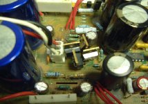
Now need to find a new method of mounting my Kwak clock so there's enough clearance below for bigger caps and order some parts.
I wonder occasionally about upgrading them, however, I still hear more and more with each CD mod, so I haven't outgrown them yet.
The grados I got cheap off of Ebay (about £60) and the amp and its PSU I built out of spare parts, and maybe £20 in extra bits. So cheap so far.
Having heard the headphones, I now know I want to replace the speakers and amp. It will be a mainly DIY affair, taking probably many years. Fed by the Marantz.
Anyway, I'm going off subject. Sorry.
Now need to find a new method of mounting my Kwak clock so there's enough clearance below for bigger caps
and order some parts.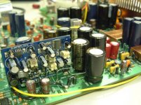
awpagan said:Music by candlelight?
What is that tube amp?
Nice amps Brent!
offtopic
Ok, can't stay behind now
 , here's some details about my setup....
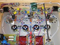
Amp: DIY Ultralinear KT88 class-A push-pull tubeamp, solid silver & teflon signal wiring, Elma & Holco stepped attenuator, Auricap coupling caps, Kiwame anode resistors, BlackGate kathode caps.
Speakers: DIY Vifa Vivace '94, silvered & teflon internal wiring, MKP & KP-SN caps, modified tweeter, bitumen and Pritex damping.
/offtopic
Regards,
Ray.
Attachments
Need to have a bit of a think about mounting.
Your clock is tiny! Mine was the first Kwak clock I made, and I used some very nice, but big polyester (I think) 1uF caps in it. There about an inch high, as well as some electrolytics.
Currently, its just mounted above the decoder using a pillar screwed to that hole in the corner.
All was fine until some of the caps grew up
For a while, I also had a small board with three 7805s and associate caps floating just outside the case by a collection of wires. Worked brilliantly, but needed mounting quick.
Will probably fit another board with regulators on somewhere as well.
Nothing is finished yet, so there is scope to do all this.
ray
very nice work
diy is very contagous, preamp amps cdp speakers.
ps how long does it take to toast your crumpets
brent
i like the layout around the sides.
shall take inspiration from that
allan
just been informed my tent clock has arrived
now need to build reg psu for it,
very nice work
diy is very contagous, preamp amps cdp speakers.
ps how long does it take to toast your crumpets
brent
i like the layout around the sides.
shall take inspiration from that
allan
just been informed my tent clock has arrived
now need to build reg psu for it,
Yep, that's the sort of thing I've done. Hopefully, will be doing a bit more of that with time
I also have decent phonos hardwired to the opamp outputs, but they have to be attached to the rear panel which is inelegant as they're soldered and chassis mounted. Fine if you don't want to dismantle things.
This is probably why I will delay the coax mod 'til later. more delicate parts.
At least its all screw terminals so it can be removed easily if needs bed (except the phonos, terminals would defeat the object).
Maybe the whole player needs re-enclosing?
Perhaps that way, there could be rather major mechanical improvements
philpoole said:Yep, that's the sort of thing I've done. Hopefully, will be doing a bit more of that with time
I also have decent phonos hardwired to the opamp outputs, but they have to be attached to the rear panel which is inelegant as they're soldered and chassis mounted. Fine if you don't want to dismantle things.
This is probably why I will delay the coax mod 'til later. more delicate parts.
At least its all screw terminals so it can be removed easily if needs bed (except the phonos, terminals would defeat the object).
Maybe the whole player needs re-enclosing?
Perhaps that way, there could be rather major mechanical improvements
agree with you totally
thought about extending connection so i could keep the pcb external while doing mods
coax connections are last
must be a major adventure for brent to remove pcb to mod

allan
awpagan said:
agree with you totally
thought about extending connection so i could keep the pcb external while doing mods
coax connections are last
must be a major adventure for brent to remove pcb to mod
allan
Its great lol
I was an audio engineer in my previous job and working on mini systems with 8-10 pcbs connected with ribbon cables and mini disc and cd mechs all attached and spread out on the bench so I can scope the fault, I find a few pcbs attached on a few wires very easy indeed
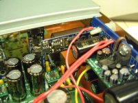
I leave the back panel attached to pcb , my reg pcbs unclip from sides, remove front facia and flip the pcb over. sorted
Re: Re: Analogue supply to the DAC
Hi Ray,
The timing diagram from the datasheet suggests that iternally the outputs are reclocked to the system clock which I presume is buffered internally, and piped around inside the chip!
Yes it will require a bit of work to produce a pcb.
I need to look at the service manual, and player (both of which I don't have at work) but I think I could interrupt the signal at the 10K resistor after the dac (remove it), and patch in a 74hc74 based reclocker circuit, and feed with a tent or kwak clock.
One Tentlabs or Kwak clock would be used to drive the dac chip, decoder, and the two reclockers for the outputs. I hope they can drive this many gates!
What I may do is build the reclocker into one channel only to see if there is any change....
6h5c said:
Yes, they are digital
There's a nice 5V square wave on the outputs, but if the duty-cycle is 50% a voltmeter will measure 2.5V.
No analog reference whatsoever...
BUT....the "analog" supply IS as critical as you mention!
Hmmm...reclocking...don't know if that will gain something.
Need another stable clock then. And more stable PSU's.
Regards,
Ray.
Hi Ray,
The timing diagram from the datasheet suggests that iternally the outputs are reclocked to the system clock which I presume is buffered internally, and piped around inside the chip!
Yes it will require a bit of work to produce a pcb.
I need to look at the service manual, and player (both of which I don't have at work) but I think I could interrupt the signal at the 10K resistor after the dac (remove it), and patch in a 74hc74 based reclocker circuit, and feed with a tent or kwak clock.
One Tentlabs or Kwak clock would be used to drive the dac chip, decoder, and the two reclockers for the outputs. I hope they can drive this many gates!
What I may do is build the reclocker into one channel only to see if there is any change....
I leave the back panel attached to pcb , my reg pcbs unclip from sides, remove front facia and flip the pcb over. sorted
Now, I have always assumed the rear panel has to be removed to take the PCB out - probably because that's what I did first time and I've stuck to it.
I wonder sometimes how I'd be if I had the ability to think!
Thanks for the tip! I am such a muppet, lol!
That solves the lovely chassis mount phono problem.
Thankfully, I've never had to work with anything more than two or three PCBs connected together at a time.
philpoole said:
Now, I have always assumed the rear panel has to be removed to take the PCB out - probably because that's what I did first time and I've stuck to it.
I wonder sometimes how I'd be if I had the ability to think!
Thanks for the tip! I am such a muppet, lol!
That solves the lovely chassis mount phono problem.
Thankfully, I've never had to work with anything more than two or three PCBs connected together at a time.
I did the same thing, always used to take the back panel off, and recently added proper phonos... but it's now 10x hard to take apart - the way it slots in mangles things under the pcb so you have to consider this. It may be the way I've modded it under there etc., but you are warned. New phonos after everything else I'd say (it's only a small improvement anyway).
Hello Ray,
thanks for clarification about the ceramics; actually i'm not planing to swap out all ceramics, but related to the diodes i did this once in my rega and it "helped";
Do you think the BG's will give me trouble in that position?
Some more questions to come, i'm afraid....
I swapped out DN03 + DN04 with Schottky by mistake, not realizing that they are not mentioned in the mod-list...can i leave them in?
I also changed the op-amps into OPA 2134 (i had them) - and the sound got worse (lifeless, grainy, harsh)!
I didn't expect that the 2134 are worse than the JRC...any of you had similar experiences?
thanks in advance,
mickie
(it's only a small improvement anyway).
Not when you used the old phonos years ago for something elsewhere and ended up using the 'remote control' phonos instead! D'oh!
Besides, I started using the new phonos when bypassing the HDAM. That way I could do a comparison. Now the HDAM is completely disconnected, and I am happier with the new connectors.
I think with this kind of project you do reach a point when its going to get progressively harder to work on the board. That's just the way it is.
Re: Re: Re: Analogue supply to the DAC
Hi Ashley,
I think the output of the DAC is at 32*Fs = 1.411MHz.
You'll need some kind of synchronisation between the system and the PWM clock, otherwise the data will go out of sync. Or divide the sysclock by twelve to obtain 1.411MHz. And then use a latch to clock the data in and out. Should be possible. Maybe it can be put to work on a breadboard.
Regards,
Ray.
ash_dac said:Hi Ray,
The timing diagram from the datasheet suggests that internally the outputs are reclocked to the system clock which I presume is buffered internally, and piped around inside the chip!
Yes it will require a bit of work to produce a pcb.
I need to look at the service manual, and player (both of which I don't have at work) but I think I could interrupt the signal at the 10K resistor after the dac (remove it), and patch in a 74hc74 based reclocker circuit, and feed with a tent or kwak clock.
One Tentlabs or Kwak clock would be used to drive the dac chip, decoder, and the two reclockers for the outputs. I hope they can drive this many gates!
What I may do is build the reclocker into one channel only to see if there is any change....
Hi Ashley,
I think the output of the DAC is at 32*Fs = 1.411MHz.
You'll need some kind of synchronisation between the system and the PWM clock, otherwise the data will go out of sync. Or divide the sysclock by twelve to obtain 1.411MHz. And then use a latch to clock the data in and out. Should be possible. Maybe it can be put to work on a breadboard.
Regards,
Ray.
mickie said:Hello Ray,
Do you think the BG's will give me trouble in that position?
Nah, no problem. That position is not critical. You should be careful around the digital chips though. Use a good electrolytic with an X7R ceramic or PPS (even better) in parallel, as close to the supply pins as possible.
Some more questions to come, i'm afraid....
I swapped out DN03 + DN04 with Schottky by mistake, not realizing that they are not mentioned in the mod-list...can i leave them in?
No problem. They are rectifiers, so it won't hurt to have schottky's there
I also changed the op-amps into OPA 2134 (i had them) - and the sound got worse (lifeless, grainy, harsh)!
I didn't expect that the 2134 are worse than the JRC...any of you had similar experiences?
thanks in advance,
mickie
Hmm, strange. When I first started modding I also tried these opamps, and OPA2604, and if I remember correctly I found them an improvement. Maybe it's because the rest of the player is not modded yet. Just put some turned-pin IC-sockets in and try again later. The power supply is also an important factor.
Regards,
Ray.
Hmm, strange. When I first started modding I also tried these opamps, and OPA2604, and if I remember correctly I found them an improvement. Maybe it's because the rest of the player is not modded yet. Just put some turned-pin IC-sockets in and try again later.
Hi Again.
Back after a day without my internet.........!!
I read an article which explained this. Unfortunately I cannot remember where - I'll post it when I find it!
The reason is the particular chips ability to handle the vast quantities of HF trash on it's input and what happens to this hash inside. For example, if the input acts as a rectifier and a cap as well, the RF is rectified and produces a DC component, however small, which affects performance downstream. Also, various parts of the chip can overload/clip due to the high level of RF.
Remember what frequencies we are talking about here. The chip may sound great in an audio preamp but was not designed to handle RF.
To be honest, I am surprised in does not happen more often.
Andy
- Home
- Source & Line
- Digital Source
- Marantz CD63 & CD67 mods list