rowemeister said:Yeah seen this. Got it book marked.
I may go for the coax soon but I want to use smaller wire.
i'am disapointed your empty headphone socket

allan
6h5c said:Hi Brent,
I don't know if silver will add anything there. It's mostly servo signals going though. I'd rather go for a shielded connection, like a piece of shielded ribbon. Maybe a separate coax for HF??
Any big sound-changes detected yet, with the blue LED's?
Ray.
Ray there is some little difference, I listened to it all last night with LEDs on. (switch being fitted today with cyan led's).
I will report with findings after weekend. I want to make sure I am right and not just believing it is better. If its worse I will say.
Everything sounded good last night though!!!!
I will get the wife to switch it on and off (without me knowing which position it is in) for the tests.
rowemeister said:Yeah seen this. Got it book marked.
I may go for the coax soon but I want to use smaller wire.
Hi.
If you are replacing the ribbon, IMO the 2 crucial cables are the +5v supply and the HF signal. If you look at the routing, the +5v is at the end of a run with the uP also taking power - noisy!! Remember, most of the RF board is analog so this +5v should be from a clean source. Similarly, the routing of the HF signal leaves a lot to be desired and is a prime candidate for coax direct to R501. I suggested this earlier in the thread.
Andy
awpagan said:I do like ray's earth point
been looking at the pcb layout to see if i can take the digital earth somewhere else
idea is use star earth on brass bar (main earth)
everthing earths to the bar.
allan
Hi.
Have I missed something or is it on the stuff Ray sent you?/
Andy
poynton said:
Yeah, I did! It scared me!
Ray.
rowemeister said:Ray there is some little difference, I listened to it all last night with LEDs on. (switch being fitted today with cyan led's).
I will report with findings after weekend. I want to make sure I am right and not just believing it is better. If its worse I will say.
Everything sounded good last night though!!!!
I will get the wife to switch it on and off (without me knowing which position it is in) for the tests.
Hi Brent,
Cool, i'm curious about the results.
awpagan said:I do like ray's earth point
allan
Thanks Allan, i'm flattered
 !
!poynton said:Hi.
Have I missed something or is it on the stuff Ray sent you?/
Andy
Hi Andy,
I scanned the PCB-layout of the CD57/67 PCB. If you want it I can send you a new CD57_67_doc.pdf, just give me a PM.
Ray.
6h5c said:
Yeah, I did! It scared me!
Ray.
I think you gentlemen have past this long ago

allan
awpagan said:I think you gentlemen have past this long ago
allan
The mods on that site are good. I like the idea of using coax for the digital signals, but I don't want my player to look like that! Maybe if I run into very thin coax some day, I will do that mod.
Ray.
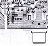
awpagan said:separate analogue from digital
allan
Hm, I wish it were that simple....
You would want to keep the top trace, cause that runs to the +/-12V groundpoint
.All the local groundpoints are also connected through the top-layer groundplane. Not bad, but they should have designed a real double-sided PCB. That would have saved a lot of wire bridges. Maybe in the future i'm going to solder some litz wire across the board.
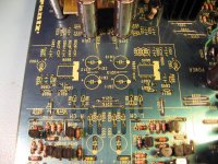
A virgin plain PCB, ready to be mounted
(with Thorsten's circuit, that is)
Attachments
burnedfingers said:I also have a Marantz CD63 special edition CD player and I am wondering what mods will deliver the best change.
Are you able to tell measured differences or are all the differences you are hearing by ear only?
Well, my mods have added 67% to sound quality, but my sound quality meter needs calibrating.
Quote:
Well, my mods have added 67% to sound quality, but my sound quality meter needs calibrating.
What were those mods if I may ask?
Well, my point is..I have seen fist fights develop over the sound of capacitors and if you blindfolded the same people they couldn't tell what the better sounding cap was.
I don't put a lot of blind faith into what people think they hear in the way of changes. Has anyone run any distortion tests to see if there was an improvement?
- Home
- Source & Line
- Digital Source
- Marantz CD63 & CD67 mods list