
Brent,
You got me thinking though....
Do all the Audiocom regs have max. 24V input, including the 12 and 15V types?
If so, it might be a good idea to lower the +/-12V windings a bit, to the original 17V. This should still enable the use of a two-stage regulator.
My CD63 measures almost +/-24V before the 12V regs in stop mode. That's a bit high compared to what the manual says. Funny thing is, my CD67 measures correctly.
Ray.

Ok well I took the cover off of my cd 53 and I recognize a few things. This first time through I am going to start with the mutting trasistors and the DC blocking caps. From looking at www.diyparadice.com it looks like I can disable the mutting trasistors by jumpering the 100ohm resistors. Is this right? if so will it sound the same as pulling them out? If I have to pull them do I just pull them out or do I have to reconnect anything?
I have a similar question about the DC ouput caps, can I leave them in and just jumper their leads or do I have to pull them out and up a jumper in?
I also am curious if anyone has considered moving the opamps into class A.
http://tangentsoft.net/audio/opamp-bias.html
Would the tecniques on this site work on these op amps?
When I replace the opamps will these be a straight drop in?
http://cimarrontechnology.com/index.asp?PageAction=VIEWPROD&ProdID=31
DJNUBZ said:................. From looking at www.diyparadice.com it looks like I can disable the mutting trasistors by jumpering the 100ohm resistors. Is this right? if so will it sound the same as pulling them out? If I have to pull them do I just pull them out or do I have to reconnect anything?
I have a similar question about the DC ouput caps, can I leave them in and just jumper their leads or do I have to pull them out and up a jumper in?
I also am curious if anyone has considered moving the opamps into class A.
http://tangentsoft.net/audio/opamp-bias.html
Would the tecniques on this site work on these op amps?
When I replace the opamps will these be a straight drop in?
http://cimarrontechnology.com/index.asp?PageAction=VIEWPROD&ProdID=31
Hi.
We do seem to have stuck on the design of a tx for the '63. However, that is a good thing as many threads seem to deteriorate into a farce of name-calling, etc. Something positive may result from this thread!!!
Remove the muting transistors - disabling will not result in any improvement.
You could jumper the caps but it would be better to remove them too. Use the holes in the pcb for the replacement jumper.
BrownDog adapters are dropin replacements.
I did ask the question re: Class A, earlier in the thread (around page 24 I think) but it has not progressed. Perhaps now the Tx issue is almost resolved, we can pick up on it.?
Andy
Hi Andy,
I think the configuration for the tranny is almost set. We should be able to close on it the coming week. Maybe it's a good idea to set up a new thread for this one, and start ordering if we reach, say, ten pieces? I don't want to wait another six weeks or so before anyone else turns up that's interested, I don't know how you feel about it?
I also want to experiment with class-A opamps, but I haven't had the time yet (too busy with some transformer... )
)
The simplest way is putting a 3k6 resistor on the output to -12V, like described, to make the opamp draw a few mA.
I read the other thread that you started, about HDAM in class-A, good idea. Should be possible if you change the DC setting of the two FET's at the output. You'll have to separate the gates and create a voltage drop between them.
Regards,
Ray.
I think the configuration for the tranny is almost set. We should be able to close on it the coming week. Maybe it's a good idea to set up a new thread for this one, and start ordering if we reach, say, ten pieces? I don't want to wait another six weeks or so before anyone else turns up that's interested, I don't know how you feel about it?
I also want to experiment with class-A opamps, but I haven't had the time yet (too busy with some transformer...
)The simplest way is putting a 3k6 resistor on the output to -12V, like described, to make the opamp draw a few mA.
I read the other thread that you started, about HDAM in class-A, good idea. Should be possible if you change the DC setting of the two FET's at the output. You'll have to separate the gates and create a voltage drop between them.
Regards,
Ray.
Hi.
I wait with baited breath for a price on the Tx. It can be offered in the Trading Post section if it will reduce the price (to the thread starters contributers?)
I really want to try Class A myself. Unfortunately, I recently moved house and I just cannot get to anything in the garage/workshop!!!!!!!!!!!!!! I even bought a bunch of 2N5484 fets (although in retrospect CR Diodes may be neater.).
On the subject of the HDAM ( which I don't want to go into too deeply here since I have started the other thread), I just feel that Marantz were on the right lines with a discreet 'opamp' but should have gone Class A !! The FET output is pure Class B !! I have been thinking of going ALL discreet along the lines the circuit shown here :-
http://ultranalog.com/cdenhancer/sacdenhancer/
But like I said .. at the moment...
Andy
Well...
I couldn't imagine that Marantz made a class-B HDAM....
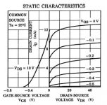
so I couldn't resist taking a look at the datasheets of the FET's, and it seems that you're wrong
The FET's are of the 'normally-on' type, so with an Ugs of 0V there will be a current flowing, somewhere between 6 and 12mA (?) for the BL version. Fweew....
Regards,
Ray.
I couldn't imagine that Marantz made a class-B HDAM....
so I couldn't resist taking a look at the datasheets of the FET's, and it seems that you're wrong
The FET's are of the 'normally-on' type, so with an Ugs of 0V there will be a current flowing, somewhere between 6 and 12mA (?) for the BL version. Fweew....
Regards,
Ray.
Attachments
I posted the wrong address
http://diyparadise.com/cdptweak.htm
and has anyone tried this?
http://diyparadise.com/rm20dac.html
http://diyparadise.com/cdptweak.htm
and has anyone tried this?
http://diyparadise.com/rm20dac.html
I have just finished my first CD player mod and it sound much better. The highs and midrange sound much better. I also seem to be getting a much sharper center image.
I now want to go on to replace the opamps. It looks like this will cost me about $31 dollars for the browndog drop ins unless somone here can recomend a cheaper opamp. While I am waiting would it be worthwhile to use a resistor to run the stock opamps in class A?
I have decided that building clock is beyond my abilities and that buying one costs way to much. So instead I plan on doing the mods on http://www.acoustica.org.uk/t/63/63hacks.html but without the extra regulator work because I'm not sure I am ready for that yet.
While I was in the CD player I saw that the c803 and c804 are 220uf caps. In the pics of the better players these look like 470uf. I have some 470uf 50V laying around. Should a R&R them?
If there are any other simple R&R parts what are they?
R&R-remove and replace.
Hi DJNUBZ,
Good to hear you like the first results of your mods. You have taken out the muting transistors and the output caps also, is that correct? Since you have a CD53, you don't have to bypass the HDAM circuit, so that will save you some work .
.
If you want to replace the opamps, I would recommend to put two IC sockets in there. That will make it easy to swap them. So you may start with a cheaper opamp now, and drop in something better in the future.
You can start with the OPA2134, AD826/827 or LT1361. But the AD8620 is very good. You can also get bare BrownDog adapters and source the opamps from Analog Devices' free sample program.
You can put the original 2114 in class-A, but I don't think that will gain much. Never tried it actually, always take it out straight away.
Why do you think you're not able to build a clock? You are soldering now, right??? All you need is a small piece of veroboard. The simplest clock would be the Tentlabs XO-module (see fuzzy picture). That's a complete oscillator in a can, all you need to add is a power-supply. Take a look on the Tentlabs Website, there's also a schematic for the PSU, and it's not too expensive. I started out with this, and it will give you far better results than the Acoustica clock hack (well, that's if you don't break anything of course).
If you change other parts, like the electrolytics, it's not only important to change them to a higher value, but also to use a GOOD capacitor. It's better to have a good 470u in there than a bad 1000u. What brand are the caps you have?
You can swap the 220u to 470u/50V, but the best thing is to use a Panasonic FC, Rubycon ZL or another type that has low ESR. The 470u will make an improvement over 220u of course, but 1000u or 2200u will be even better, and you get the best results if you use a special low-ESR cap.
For other parts that are easy to replace, you can take a look at one of my mods list. The CD57 list is the most recent one I did. You can start with the power supply caps, and around the opamps. Do the the bigger ones first, and do the smaller parts later, like the 4,7R resistors. If you get the hang of it you can really dig in.

Regards,
Ray.
Good to hear you like the first results of your mods. You have taken out the muting transistors and the output caps also, is that correct? Since you have a CD53, you don't have to bypass the HDAM circuit, so that will save you some work
.If you want to replace the opamps, I would recommend to put two IC sockets in there. That will make it easy to swap them. So you may start with a cheaper opamp now, and drop in something better in the future.
You can start with the OPA2134, AD826/827 or LT1361. But the AD8620 is very good. You can also get bare BrownDog adapters and source the opamps from Analog Devices' free sample program
.You can put the original 2114 in class-A, but I don't think that will gain much. Never tried it actually, always take it out straight away
.Why do you think you're not able to build a clock? You are soldering now, right??? All you need is a small piece of veroboard. The simplest clock would be the Tentlabs XO-module (see fuzzy picture). That's a complete oscillator in a can, all you need to add is a power-supply. Take a look on the Tentlabs Website, there's also a schematic for the PSU, and it's not too expensive. I started out with this, and it will give you far better results than the Acoustica clock hack (well, that's if you don't break anything of course
).If you change other parts, like the electrolytics, it's not only important to change them to a higher value, but also to use a GOOD capacitor. It's better to have a good 470u in there than a bad 1000u. What brand are the caps you have?
You can swap the 220u to 470u/50V, but the best thing is to use a Panasonic FC, Rubycon ZL or another type that has low ESR. The 470u will make an improvement over 220u of course, but 1000u or 2200u will be even better, and you get the best results if you use a special low-ESR cap.
For other parts that are easy to replace, you can take a look at one of my mods list. The CD57 list is the most recent one I did. You can start with the power supply caps, and around the opamps. Do the the bigger ones first, and do the smaller parts later, like the 4,7R resistors. If you get the hang of it you can really dig in.
Regards,
Ray.
Attachments
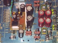
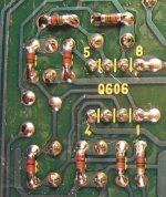
Ray your caps and resistors look very similar to mine
Silver mica caps and 0.1% tol resistors.
Silver mica caps and 0.1% tol resistors.
An externally hosted image should be here but it was not working when we last tested it.
An externally hosted image should be here but it was not working when we last tested it.
Yeah, you're right
This is my CD67SE by this way. You also used the Welwyn resistors?
In my CD57 I used 0,1% SMD's, works also very well, and MKP caps, just to see if there's a sonical difference. Still have to do a comparison between the two.
Ray.
This is my CD67SE by this way. You also used the Welwyn resistors?
In my CD57 I used 0,1% SMD's, works also very well, and MKP caps, just to see if there's a sonical difference. Still have to do a comparison between the two.
Ray.
Attachments

Ray
I always clean mine too. I dont know about you but here in the UK the solder is now lead free and it's crap. Its 60/40 Tin Copper.
The solder is much duller to look at and it annoys me
It cools and sets much quicker than the lead.
I have some OPA127 but used the OPA627 _ OPA132 set up and have not listened to them.
Also C605 etc with the inductor, I remember you said you shortened out the inductor and changed the cap for nearly half value, is this correct?
- Home
- Source & Line
- Digital Source
- Marantz CD63 & CD67 mods list