Franz G said:
One very interesting detail, I was not aware before: I inserted a Kwak Clock with the original quartz.
But the original Quartz is not precisely enough! It is a 16.935Mhz and not 16.9344! I does absolutely make no sense, to insert the original quartz into a Kwak, for this player!
Franz
P.S.
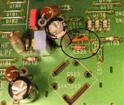
Interesting detail: C522 and C523 are obsolete in any case, they don't exist in any service manual and should not be there!
Hi Franz,
That's a 600Hz error or 0,0035%. Do you think you can hear that? If you put up the heating in your room, the error would be more due to temp. coefficient.
Did your check if the number on the PCB matches the manual? The PDF-manual that most of us have covers the CD63 main PCB WG286K101-0. The PCB with the extra C522/523 (and extra C521 or RD14 near the DAC) is the CD63-MKII WG286K101-2. Mine also has a resistor in place of U193.
There are two or three CD63 board revisions with minor changes in the circuit and layout, and this one uses capacitive coupling of the clock signal. Don't know which method is better though. Anyone has a clue?
Regards,
Ray.
Attachments
Re: Pokin' around....
Fantastic! Any discernable sonic benefits? I'm gonna do some work on mine now... wish me luck
6h5c said:Did some more pokin' around with the solder-gun this afternoon....
Used 0805 100n X7R, fit's perfectly.
Thanks to Guido!
Ray.
Fantastic! Any discernable sonic benefits? I'm gonna do some work on mine now... wish me luck
6h5c said:I see you have C901/902 still in there, that lead to the headphone part. These traces run alongside the DAC and will take some noise with them, right into the analog part. If you take them out you can prevent that. While you are at it, take out U139/140 to disable the +/- 12V.
Hello Ray,
Whilst following one of your nice PDF files, I removed U139 and U140, then remembered it was mods for the CD57, so I put them back in. In your CD63 list you say the jumpers to remove for the headphone 12v are U271/272.
I thought this was worth pointing out as Rowermeister uses a CD63, not a CD57, and some part numbers may be different, as above.
I have this evening removed C901, C902, U271, U272, QN24, QN25, QN91, QN92, RN27, RN28 and U207. I can't find U262

So that's the muting circuit disarmed, and the headphone circuit taken out too. Next to deal with is the hdam.
edit: would the fact that I'd not taken all the muting parts out explain why it didn't affect the sound? All I'd done previously was remove QN05, 6, 7, 8.
Hi guys,
I did some more:
removed R651, R652, R653, R654 (12v into hdam), R617, R618 (signal into hdam), RH23, RH24 (signal from hdam), U210, U214 (signal before hdam).
I added a length of silver wire from where U210/214 starts to a 100R resistor, which is then soldered directly onto the phono socket.
Hopefully in doing this I've not bypassed anything important. I can't find my pdf of the service manual ..but hopefully all I've avoided is resistors that take the signal to the headphone socket and some other non-essential stuff. When I'm more sure I could cut the traces leading to the jacks, to avoid pollution being added.
Will get it hooked up and go to bed now, whether it works or not.
I did some more:
removed R651, R652, R653, R654 (12v into hdam), R617, R618 (signal into hdam), RH23, RH24 (signal from hdam), U210, U214 (signal before hdam).
I added a length of silver wire from where U210/214 starts to a 100R resistor, which is then soldered directly onto the phono socket.
Hopefully in doing this I've not bypassed anything important. I can't find my pdf of the service manual
..but hopefully all I've avoided is resistors that take the signal to the headphone socket and some other non-essential stuff. When I'm more sure I could cut the traces leading to the jacks, to avoid pollution being added.Will get it hooked up and go to bed now, whether it works or not.
SimontY said:
Hello Ray,
Whilst following one of your nice PDF files, I removed U139 and U140, then remembered it was mods for the CD57, so I put them back in. In your CD63 list you say the jumpers to remove for the headphone 12v are U271/272.
I thought this was worth pointing out as Rowermeister uses a CD63, not a CD57, and some part numbers may be different, as above.
Hi SimontY,
You are absolutely right, these are nasty little differences between the two boards. It's why I decided to make separate lists.
I have this evening removed C901, C902, U271, U272, QN24, QN25, QN91, QN92, RN27, RN28 and U207. I can't find U262
So that's the muting circuit disarmed, and the headphone circuit taken out too. Next to deal with is the hdam.
edit: would the fact that I'd not taken all the muting parts out explain why it didn't affect the sound? All I'd done previously was remove QN05, 6, 7, 8.
U262 sits in the back, between C656/685, the output capacitors. It transports the 'R' muting signal to the headphone section, just like U207 does for the left channel. Don't forget to decouple the muting lines (see list), they run parallel with the digital-out trace.
It's not likely that you will hear direct result from these kind of mods. The differences are small, but you can imagine if you do ten of these mods it will clean things up more noticeably.
You should be able to hear the initial removal of muting transistors though. What other gear/interconnects do you use?
The mods seem correct. You can find the PDF here
Regards,
Ray.
6h5c said:
Hi SimontY,
You are absolutely right, these are nasty little differences between the two boards. It's why I decided to make separate lists.
Good, I thought it was worth checking.
U262 sits in the back, between C656/685, the output capacitors. It transports the 'R' muting signal to the headphone section, just like U207 does for the left channel. Don't forget to decouple the muting lines (see list), they run parallel with the digital-out trace.
Ahha, so that's where he hides, I'll take that out when I get home.
It's not likely that you will hear direct result from these kind of mods. The differences are small, but you can imagine if you do ten of these mods it will clean things up more noticeably.
You should be able to hear the initial removal of muting transistors though. What other gear/interconnects do you use?
Fair enough. I had no trouble hearing the majority of mods.
The Marantz feeds a Rod Elliot project 88 pre-amp, which uses LM6172 in each gain stage currently, connected via a Chord Silver Siren interconnect. The power amp is connected via a Kimber Crystal-Cu, and the power amp is an mdf chassis LM3886, dual mono, with 'snubber'
The speakers are connected by Kimber 4pr and 4vs, and they are Seas Pontus MTM, but with a redone x-over, mixing 1st and 2nd order @ 5khz. 15" diy sub for 50hz and down. Some room diffusion panels, and pre-amp and cdp are on their own iso. transformers, and there's some parallel mains cleaning. My system wasn't as good at the time of the earliest mods though, as I was using a commercial integrated amp, and other parts weren't as nice.Thanks very much for your help. Someone also e-mailed me the service manual. It's a good thing to have because my player now doesn't work, so I have some fault finding to do!
Hi,
& did most of these modifications(decoupling capacitors Elna rsh and wima fks for digital part,big electrolytes Elna rjh,LM317,LCaudio XO2 clock with separate power supply,separate clock,digital and analogue power supplies for dac,ad826 opamps,BC MKP capacitors for filter,elna silmic capacitors for analogue power supply,remove headphone,mute circuts,shorten output capacitors).It did great improvement.
After that & tried dac with TDA1543 http://www.diyparadise.com/rm20dac.html
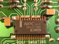
I/u resistors 2k2 (Allen Bradley carbon),signal capacitors 4,7uF M-Cap MKP) and no analogue filter.It did a great improvement.& disconnected power from SM5872 and connect clock directly to SAA7345 pin.Now sound more dynamic,instruments more natural.This is very recommended tweak and cheap.
& did most of these modifications(decoupling capacitors Elna rsh and wima fks for digital part,big electrolytes Elna rjh,LM317,LCaudio XO2 clock with separate power supply,separate clock,digital and analogue power supplies for dac,ad826 opamps,BC MKP capacitors for filter,elna silmic capacitors for analogue power supply,remove headphone,mute circuts,shorten output capacitors).It did great improvement.
After that & tried dac with TDA1543 http://www.diyparadise.com/rm20dac.html
I/u resistors 2k2 (Allen Bradley carbon),signal capacitors 4,7uF M-Cap MKP) and no analogue filter.It did a great improvement.& disconnected power from SM5872 and connect clock directly to SAA7345 pin.Now sound more dynamic,instruments more natural.This is very recommended tweak and cheap.

Originally posted by SimontY
Thanks very much for your help. Someone also e-mailed me the service manual. It's a good thing to have because my player now doesn't work, so I have some fault finding to do!
Hi SimontY,
Any luck on your player yet?
Ray.
Hello Ray,
Nope, can't see what the problem is yet, but I only started looking recently. The iron is hot, so I should strike now!
At least I can see U262 now, thanks! I'll take that out. And I found my camera today (thought I'd maybe lost it) so I can take a pic of my laughably messy work.
Nope, can't see what the problem is yet, but I only started looking recently. The iron is hot, so I should strike now!
At least I can see U262 now, thanks! I'll take that out. And I found my camera today (thought I'd maybe lost it) so I can take a pic of my laughably messy work.
I found this page to be helpful:
http://www.tnt-audio.com/clinica/cd67.html
I did the blutack mods, putting sound deadening inside the chassis, replacing RC filters with LC filters, snipping the output muting transisters, replacing the fixed mains cable with a noise-suppressing input, and replacing some capacitors with slightly larger higher quality caps.
Overall for the effort and cost, it was a very worthwhile improvement at the time. BTW Marantz sent me the schematics for free simply by asking for them.
Simon..
I don't think the HDAM bypass is causing your fault!
I believe there is probably a dry joint or cracked track around the 12V/5V supplies from flexing the pcb when doing this last mod.
Have alook around Q801 Q802 Q811. Turn the pcb upside down and move the regs slightly and look carefully for any movement on the pcb tracks around the solder.
Also the connectors to the laser etc could have a similar problem.
SimontY said:Evening
Still no joy finding what's wrong with the player, but I don't really know how to fault-find it.
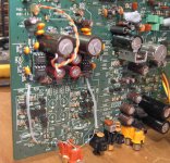
Here it is in it's current state with the jumpered buffer etc.
Think I found it! Your clock isn't attached!

- Home
- Source & Line
- Digital Source
- Marantz CD63 & CD67 mods list