Yes, it's different for the CD63, that's why it says 'CD57/67 series' ;-)
For the CD53/63 series you need to:
- remove U116, U124 and DF52 to isolate the RC-5 signal
- remove RF52, RF54 and RF61 to disable the 5V power supply for this circuit
- insert a jumper wire from U116 (the hole farthest from QF61) to U124 (the hole near U121)
You should have a working remote after this, if not, then something else is wrong.
Regards,
Ray
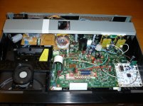
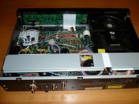
In my post #20358 I mentioned that I will replace the stock TX of the CD63 with 3 coroidal TXs:
http://www.diyaudio.com/forums/digi...ntz-cd63-cd67-mods-list-2036.html#post3953824
The 3 TXs have eventually come and I have now completed the modding project for my friend. It works wonderfully well as expected. No issues at all. My friend is really happy with it. The total cost inclusive of parts and the CD63SE is about £300 (of course excluding my labor cost") ) I think in total I have spent about 2-3 days to complete the job.
) I think in total I have spent about 2-3 days to complete the job.
http://www.diyaudio.com/forums/digi...ntz-cd63-cd67-mods-list-2036.html#post3953824
The 3 TXs have eventually come and I have now completed the modding project for my friend. It works wonderfully well as expected. No issues at all. My friend is really happy with it. The total cost inclusive of parts and the CD63SE is about £300 (of course excluding my labor cost
) I think in total I have spent about 2-3 days to complete the job.Attachments
In my post #20358 I mentioned that I will replace the stock TX of the CD63 with 3 coroidal TXs:
http://www.diyaudio.com/forums/digi...ntz-cd63-cd67-mods-list-2036.html#post3953824
The 3 TXs have eventually come and I have now completed the modding project for my friend. It works wonderfully well as expected. No issues at all. My friend is really happy with it. The total cost inclusive of parts and the CD63SE is about £300 (of course excluding my labor cost
Nice job, Higlander!
Has anyone (UV101?) set up a separate tx to power the laser and motor drive? I believe this will require 6 regulators! So it's not going to be cheap.
If anyone has done so, what difference did it make? I know when I set up a sep tx and power supply for the servo it made a big difference. I have also set up separate txs and power supplies for the output stage (with HDAM bypass), DAC digital, DAC analogue, decoder (big difference!), the servo clock and DAC clock. I am currently in the process of setting up Ray's DOS board.
So what I'd like to know is whether the cost to power the laser and motor drive will be worth the SQ improvement. Thanks in advance.
CD67OSE Upgrades - Issues on 1st power up
Hi folks, I'm in need of some troubleshooting help:
I've just finished modding a CD67OSE using Ray's pdf instructions (the CD57 version though). I have not made any modifications to the analogue sections or clock yet.
On power up the player displays "Disc". I press eject and the tray opens. I insert a CD and press eject and the tray closes. BUT the turntable motor makes no attempt to turn and read the CD and so "Disc" remains on the display. I have seen that the laser is working so I was wondering if the problem was with the servo drivers and/or the micro controller.
I have checked the polarity of the electrolytics I've installed in those sections and everything seems to be okay.
I will try putting the player in to service mode tonight to see if that points me to the problem part of the circuit.
Anyone else experienced this before? or might know which part of the player I may have made a mistake on?
I deviated from Ray's instructions in one area - I ran out of ferrite beads and so the inductor installed at RY11 has no beads - could this be an issue?
I modded a cd67 15 or 16 years ago(Thorsten Loesch) , I had the same thing, discovered if I powered the unit off then back on quite quickly it would work, occasionally it took two attempts, my own theory is the larger capacity capacitors are consuming the power when you first switch on(but then I know very little).
I still use the player in it's original modded form but may get around to addressing the problem when I have finished modding a cd63.
Last edited:
I just found this thread, I purchased a Marantz CD 63, I was surprised to find
when I opened it up that all the Caps are Elna Silmic's in it (redone?) the problem
is that it has is a balance issue sound seems to go to the left of center, can it be
as simple as the input rca's or another problem??
Al
when I opened it up that all the Caps are Elna Silmic's in it (redone?) the problem
is that it has is a balance issue sound seems to go to the left of center, can it be
as simple as the input rca's or another problem??
Al
Hi folks, I'm in need of some troubleshooting help:
I've just finished modding a CD67OSE using Ray's pdf instructions (the CD57 version though). I have not made any modifications to the analogue sections or clock yet.
On power up the player displays "Disc". I press eject and the tray opens. I insert a CD and press eject and the tray closes. BUT the turntable motor makes no attempt to turn and read the CD and so "Disc" remains on the display. I have seen that the laser is working so I was wondering if the problem was with the servo drivers and/or the micro controller.
I have checked the polarity of the electrolytics I've installed in those sections and everything seems to be okay.
I will try putting the player in to service mode tonight to see if that points me to the problem part of the circuit.
Anyone else experienced this before? or might know which part of the player I may have made a mistake on?
I deviated from Ray's instructions in one area - I ran out of ferrite beads and so the inductor installed at RY11 has no beads - could this be an issue?
It won't be the beads. Try checking the voltages at variuos places in the circuit (and expecially going to the servos that control the turntable motor).
ok so I put the player in to service mode last night and got error 2 - focal. After messing about with various connections, I powered the unit up again without the transport attached (I can't remember why actually lol). Anyway when I re-connected plug JM01, the radial motor actuated and moved the lens all the way to the end of the transport (and obviously tried to keep going). I turned the unit off again.
Since that time, whenever I put the player in to service mode I now get error 12 - sled motor.
I checked all the voltages of QF01 and they are the correct order, however the +5.0V pins all read about 4.8 - 4.9V. The regulators themselves are putting out 4.97V. Is this voltage drop usual?
Finally, the voltages of pins 13 & 16 of Q106 are reading 0.7V but I think they ought to be 2.5 and 2.4V? They relate to TT+ and TT- according to the service manual, which I assume are the signals to modulate the disc motor speed?
An externally hosted image should be here but it was not working when we last tested it.
An externally hosted image should be here but it was not working when we last tested it.
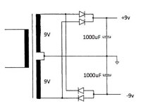
Hi Ray, I want to use your Flea kit and TentXO. You recomment a dedicated transformer and I have a small 2X9v 3Va toroidal handy. Would the attached scheme be enough to power? Thanks! Henry
An externally hosted image should be here but it was not working when we last tested it.
Sorry if I seem like I'm talking to myself...
Q106 is outputting 0.7V at pins 13 & 16 because it is only receiving 1.6V at pins 1 & 2 instead of 2.5V.
This leads back to QF102 only having 1.6V at its 'MOTO1 & 2" signal pins...I've verified this by measuring the voltage either side of R115 and R116.
I don't know why this voltage is 0.9V too low though??
Has anyone (UV101?) set up a separate tx to power the laser and motor drive? I believe this will require 6 regulators! So it's not going to be cheap.
If anyone has done so, what difference did it make? I know when I set up a sep tx and power supply for the servo it made a big difference. I have also set up separate txs and power supplies for the output stage (with HDAM bypass), DAC digital, DAC analogue, decoder (big difference!), the servo clock and DAC clock. I am currently in the process of setting up Ray's DOS board.
So what I'd like to know is whether the cost to power the laser and motor drive will be worth the SQ improvement. Thanks in advance.
I don't have any experience with this, so I can't tell you if it will make a big difference. I know that adding two regulators to feed the drivers will help, but i'm not sure if there will be a further improvement if you feed each of the driver-IC's separately. You could start by adding an extra supply for the driver of the disc motor (QM01), or the one that drives the focus and radial coils (Q106) and see what happens.
Sorry if I seem like I'm talking to myself...
Q106 is outputting 0.7V at pins 13 & 16 because it is only receiving 1.6V at pins 1 & 2 instead of 2.5V.
This leads back to QF102 only having 1.6V at its 'MOTO1 & 2" signal pins...I've verified this by measuring the voltage either side of R115 and R116.
I don't know why this voltage is 0.9V too low though??
This could be a sign that one of the supply-voltages of the decoder is missing.
Hi Ray, I want to use your Flea kit and TentXO. You recomment a dedicated transformer and I have a small 2X9v 3Va toroidal handy. Would the attached scheme be enough to power? Thanks! HenryAn externally hosted image should be here but it was not working when we last tested it.
Hi Henry,
The power of the tranny is enough, but you don't need a symmetrical supply like the +/-9V of your schematic. Just connect the two 9V windings in series to make 18V, like you have now, and use one bridge rectifier and one capacitor. Forget the center tap to ground. Then use a 7818 to get a nicely regulated voltage for The Flea.
See here.
I just found this thread, I purchased a Marantz CD 63, I was surprised to find when I opened it up that all the Caps are Elna Silmic's in it (redone?) the problem is that it has is a balance issue sound seems to go to the left of center, can it be as simple as the input rca's or another problem??
Al
Is it a standard CD63 or CD63 Special Edition? Marantz uses some Silmic's as output caps and Cerafines around the opamps originally.
The RCA's are known for getting loose, check the soldering of the pins at the underside of the board. If they are allright, the cause could be anywhere in the analog circuit, from the DAC that has a defective output to one of the opamps gone bad. Maybe there's a loose part in the analog filter around the opamps. You should inspect the board for loose contacts and check the supply voltages.
Last edited:
- Home
- Source & Line
- Digital Source
- Marantz CD63 & CD67 mods list