Just now when I put my modded CD63 into service mode and run at P03 I heard a slight explosion sound inside the CDP. I opened it up and found the opamp QM01 was blown off the top. I suspect the sew motor was stuck and overloading the opamp. I will order a new opamp and replace the damage one. I will also change the whole laser unit to ensure everything in particular the motor works okay. I think this is very unusual and don't think anyone here had ever encountered the same defect before. It will be a big disassembling job and will take some time to complete the repair.
Lymmlad, fairplay, that's some serious work there!
After being left for a day, my faulty player has just started working again. I'm glad it's working, but I really hate intermittent faults
It was pretty cold in the workshop where my hifi gear lives, so this says to me I've got a crappy soldered joint somewhere. Possibly just the clock signal to the servo or decoder.
I'll pull the board when I have a spare evening and reflow a few joints.
While I'm there, have people really noticed a difference with replacing the digital signal from decoder to DAC with shielded coax?
While I'm there, have people really noticed a difference with replacing the digital signal from decoder to DAC with shielded coax?
I used a shielded coax from the DAC to the digital sockets for all of my CD63s. Theoretically it should be better than the thin copper strip on the PCB but I did not use any instrument to verify the differences. Just cut the copper strip and replace by the shielded coax. However my ears cannot tell any difference but there is no harm to do a bit of work to have peace of mind.
Do you mean the sockets on the back of the player? If so, I've disabled those already by cutting the trace at the decoder as I definitely won't be using them.I used a shielded coax from the DAC to the digital sockets for all of my CD63s. Theoretically it should be better than the thin copper strip on the PCB but I did not use any instrument to verify the differences. Just cut the copper strip and replace by the shielded coax. However my ears cannot tell any difference but there is no harm to do a bit of work to have peace of mind.
I still used the sockets and what I did was to cut the trace just before the RCA and the optical socket as well the trace from the digital o/p from the DAC. I inserted a coax cable to replace the trace.Do you mean the sockets on the back of the player? If so, I've disabled those already by cutting the trace at the decoder as I definitely won't be using them.
Thought I'd share what I have done to avoid all that spaghetti shown in some previous posts!
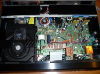
This is my player with the main tx removed to another box. The brown and blue wires at top left are the AC feeds from the main tx which are attached to their respective original power rails. The red wires are separate feeds from separate trannies for the servo, the output stage and DAC analogue and DAC digital. The silver wires are the clock feeds (servo and DAC). All connections are XLRs. My mentor/guru reddish, an occasional poster on here, has been of tremendous help to me.
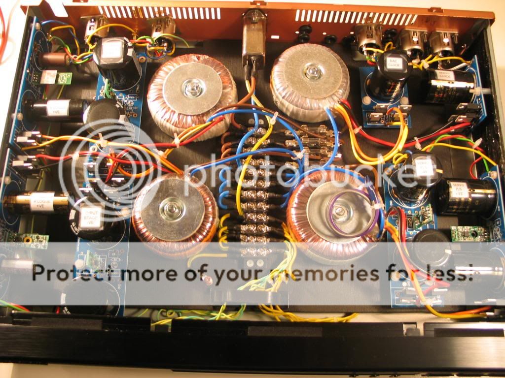
This is my second player with guts removed and a false floor constructed. This carries txs powering the 2 clocks (top right), the servo (bottom right), the output stage (top left) and the 2 analogue DAC rails (bottom left). All the AC is in this box, with only DC feeds into the main player (all the red and silver wires).
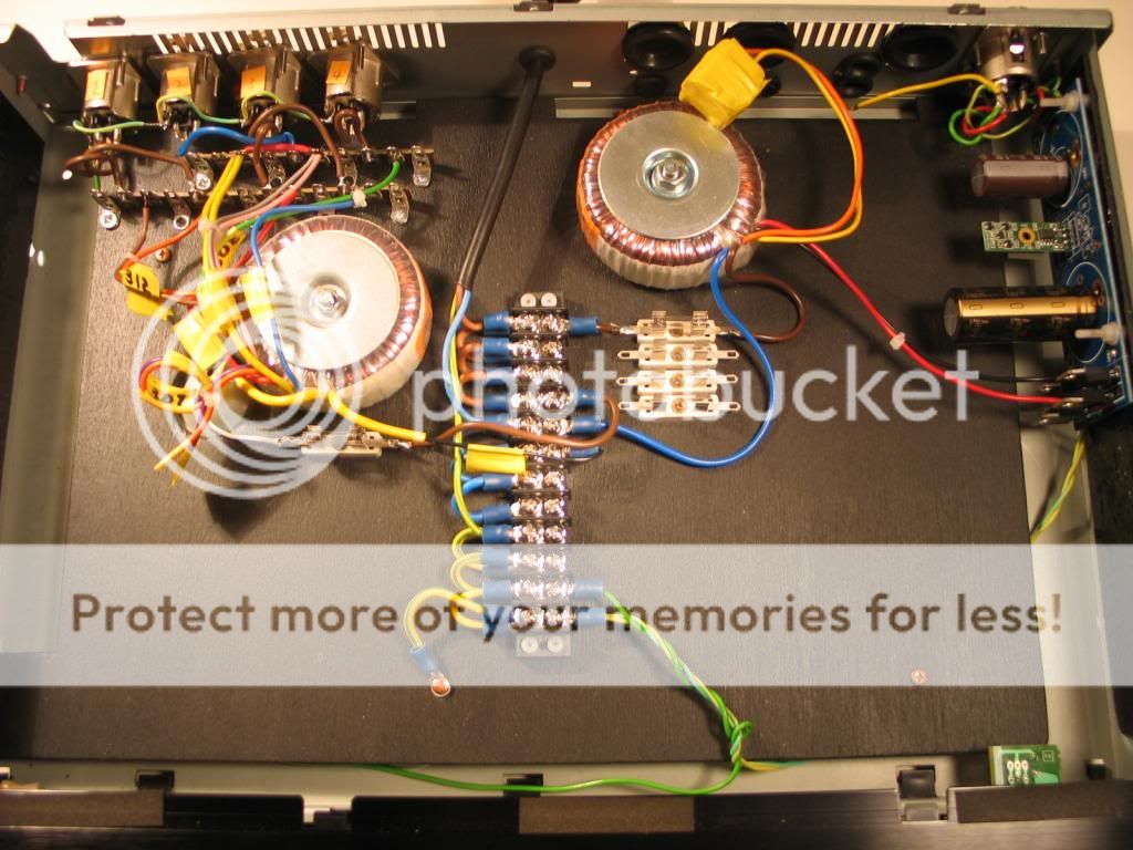
This is my third player with guts removed and a false floor constructed. This carries the re-located main tx (on left) and a tx (on right) feeding the digital DAC rail. I have yet to fit a filtered IEC socket to this box as I have done with the other box. Eventually the 2 'transformer' boxes will each have an on/off switch. The diode indicating 'on' will be neatly fitted into the headphone socket. Note: more room for more trannies in this box! Note also the star earthing.


Cool work
That is what I need to do
Alive!
Finally my player is alive again!
I experienced number of faults in a row.
Finally my player is alive again!
I experienced number of faults in a row.
- First the Q106 blew. After I ordered and replaced the player still showed focus error.
- Found out the laser was dead. I ordered and replaced with VAM1202. Still didn't work. This was getting really frustrating.
- Hard wired between Mech and PCB. Voila! The player was working again but only sound in one channel. Left channel was dead. Measured voltages around op-amp. They were way off.
- Replaced op-amp for left channel. That fixed that. Now the player is sounding better than ever.
CD rotates anti-clockwise when stop
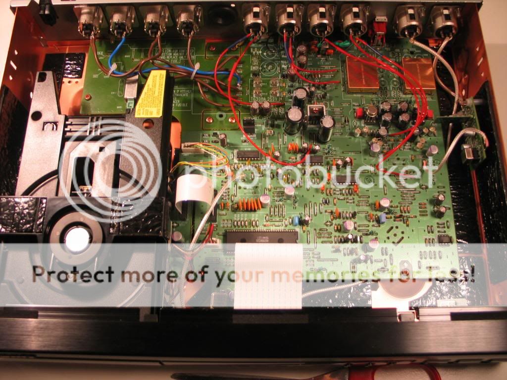
Two months ago I mentioned that an opamp QM01 (TCA 0372) of my CD63SE had blown up (with sparks). I had no idea what was the cause of it Today I made up my mind and spent some time fixing the defective CDP. I also took the opportunity changing the laser unit to a brand new one.
Well, the CDP plays CD without any problem and the SQ is the same as before. Everything seems to return normal however I found that when the CDP is stopped the CD rotates slowly anti-clockwise. I have not touched anything apart from changing the IC QM01 and the laser unit. Any ideas what is the likely the cause of the rotation and how to fix it ??
The unit is fitted with 2 fleas from RAY and I remembered that the CD did not rotate before QM01 was blown. I uploaded my fixed CDP here for your reference.
According to the circuit diagram QM01 controls the tray motor as well as the Disk Motor. My be my new laser unit dees not work well with the circuit.
Two months ago I mentioned that an opamp QM01 (TCA 0372) of my CD63SE had blown up (with sparks). I had no idea what was the cause of it
Today I made up my mind and spent some time fixing the defective CDP. I also took the opportunity changing the laser unit to a brand new one.Well, the CDP plays CD without any problem and the SQ is the same as before. Everything seems to return normal however I found that when the CDP is stopped the CD rotates slowly anti-clockwise. I have not touched anything apart from changing the IC QM01 and the laser unit. Any ideas what is the likely the cause of the rotation and how to fix it ??
The unit is fitted with 2 fleas from RAY and I remembered that the CD did not rotate before QM01 was blown. I uploaded my fixed CDP here for your reference.
According to the circuit diagram QM01 controls the tray motor as well as the Disk Motor. My be my new laser unit dees not work well with the circuit.
Attachments
Last edited:
- Home
- Source & Line
- Digital Source
- Marantz CD63 & CD67 mods list