I don't think you have changed the filtering caps for the sero, the DAC and decoder. Just compare your PCB and mine and you will find I have changed a lot of the stock caps in brown color by OSCON SEPC 470uF. It will improve the SQ.Sorry for my ignorance, but does this mean I also have to "change the filtering caps for the servo, DAC and decoders etc"? Have I not done this already?
I have not done anything about the power supply for the output stage yet. When I set up a separate transformer, diodes, smoothing cap, s-power regulators, etc, will this make an appreciable difference?
Thanks again for your comments.
If you can improve the power supply for the output stage there is no doubt that you will hear a lot of difference unless you just use your CD63 as a transport then there is not need to do anything on the output stage.
lymmlad@: One more thing it seems to me that you have not had independent 5V low noise regulated power supply to the servo, the DAC and the decoder. Look at the circuit diagram in the service manual and you can easily find where should the 5V power supplies go. You need 6 s-Powers to supply these circuits. Furthermore you can have another s-Power connected to the RF circuit if you wish.
Higlander, Thanks again for your comments.
"I don't think you have changed the filtering caps for the sero, the DAC and decoder. Just compare your PCB and mine and you will find I have changed a lot of the stock caps in brown color by OSCON SEPC 470uF. It will improve the SQ."
Yes, I've checked your pcb, and I see what you mean. Later I will check and identify which individual components you have changed. Are they all the same value Oscons: 470uF?
"If you can improve the power supply for the output stage there is no doubt that you will hear a lot of difference unless you just use your CD63 as a transport then there is not need to do anything on the output stage."
I will be using my CD63Ki as a player and not just as a transport. So it seems it will be beneficial to do this.
"One more thing it seems to me that you have not had independent 5V low noise regulated power supply to the servo, the DAC and the decoder. Look at the circuit diagram in the service manual and you can easily find where should the 5V power supplies go. You need 6 s-Powers to supply these circuits. Furthermore you can have another s-Power connected to the RF circuit if you wish."
I will need to check this out with my mentor, as I don't yet have the technical know-how to fully understand and implement this. Thanks again for your helpful suggestions.
Yes, I've checked your pcb, and I see what you mean. Later I will check and identify which individual components you have changed. Are they all the same value Oscons: 470uF?
OSCON is preferred for filtering digital circuits while Rubycon is better in analogue rail (which you have already installed).
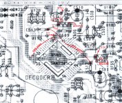
Could someone explain the correction for the Decoder IC please?
I can see the picture here:
but I'm missing the 'cut this' and 'join this bit to that' bit.
Is it as straightforward as cutting at the pink X and running a small wire over the chip along the pink path?
What's the extra blue track for?
thanks,
James
I can see the picture here:
An externally hosted image should be here but it was not working when we last tested it.
but I'm missing the 'cut this' and 'join this bit to that' bit.
Is it as straightforward as cutting at the pink X and running a small wire over the chip along the pink path?
What's the extra blue track for?
thanks,
James
Last edited:
Hi guys, it has been a while ago, but I'd like to try one more mod ") The player sounds very good, but the bass could be a bit tighter. I regulated the drivers already, but I'd like to experiment with a separate power supply. I don't have much knowledge of how to do this. I do have this power supply for my DDdac (see attachment). Can I use it to experiment? I can only do the +10V supply with it I guess, is that a problem? Adjust the supply at +10V and put the ground to any ground in the Maranz?
The player sounds very good, but the bass could be a bit tighter. I regulated the drivers already, but I'd like to experiment with a separate power supply. I don't have much knowledge of how to do this. I do have this power supply for my DDdac (see attachment). Can I use it to experiment? I can only do the +10V supply with it I guess, is that a problem? Adjust the supply at +10V and put the ground to any ground in the Maranz?
Tnks!
The player sounds very good, but the bass could be a bit tighter. I regulated the drivers already, but I'd like to experiment with a separate power supply. I don't have much knowledge of how to do this. I do have this power supply for my DDdac (see attachment). Can I use it to experiment? I can only do the +10V supply with it I guess, is that a problem? Adjust the supply at +10V and put the ground to any ground in the Maranz?Tnks!
Attachments
Could someone explain the correction for the Decoder IC please?
I can see the picture here:
An externally hosted image should be here but it was not working when we last tested it.
but I'm missing the 'cut this' and 'join this bit to that' bit.
Is it as straightforward as cutting at the pink X and running a small wire over the chip along the pink path?
What's the extra blue track for?
thanks,
James
See my sketch below and you will understand what it means
Attachments
If you want to have tighter bass I suggest you give the servo with a steady power supply by using a 50VA 2X12V toroidal Tx.Hi guys, it has been a while ago, but I'd like to try one more mod
Tnks!
See my sketch below and you will understand what it means
Perfect, thank you.
Even answers my next question about where to add seperate regs for the digital and analog sections too
Cheers,
James
Actually, now I follow that all through with a fresh head, something there doesn't make sense...See my sketch below and you will understand what it means
Where you have shown a new +5v to the place where the R511 is removed, shouldn't it be to the other hole left by the R511? Otherwise with the R511 removed, there's no path to the + of the C509, C510 and pin 11 of the decoder?
You may wish to check the copper straps in the PCB and I think you may retain the resistor or remove it. The resistor is for protection the supply circuit.Actually, now I follow that all through with a fresh head, something there doesn't make sense...
Where you have shown a new +5v to the place where the R511 is removed, shouldn't it be to the other hole left by the R511? Otherwise with the R511 removed, there's no path to the + of the C509, C510 and pin 11 of the decoder?
All I mean is, shouldn't the new 5v where R511 is removed go to this green point instead?You may wish to check the copper straps in the PCB and I think you may retain the resistor or remove it. The resistor is for protection the supply circuit.
Yes, you are right. You should connect the +5V to the green point if you want to bypass the R511 resistor. Alternative you can lift one of the the legs of R511 (the leg on the left hand side) and connect the +5V to it. This serves as a protection to limit the current in case of a short circuit. Sorry for the confusion.All I mean is, shouldn't the new 5v where R511 is removed go to this green point instead?
Last edited:
no trouble. that's great. ThanksYes, you are right. You should connect the +5V to the green point if you want to bypass the R511 resistor. Alternative you can lift one of the the legs of R511 and connect the +5V to it. This serves as a protection to limit the current in case of a short circuit. Sorry for the confusion.
Do you happen to know how many mA the digital and analog sections of the decoder use on their 5v feeds?
I think the current drawn from individual ICs of the DAC, the Decoder and the Servo IC should be less than 200mA as I constructed my low noise voltage regulator using LT17635 which has a max. output of 500mA only.no trouble. that's great. Thanks
Do you happen to know how many mA the digital and analog sections of the decoder use on their 5v feeds?
You may look at thread number 19021 and 19029 to see what I had done with the LT17635 regulators which is located on top of the display control chip.
http://www.diyaudio.com/forums/digital-source/54009-marantz-cd63-cd67-mods-list-1903.html
Last edited:
ooooh, niceI think the current drawn from individual ICs of the DAC, the Decoder and the Servo IC should be less than 200mA as I constructed my low noise voltage regulator using LT17635 which has a max. output of 500mA only.
You may look at thread number 19021 and 19029 to see what I had done with the LT17635 regulators which is located on top of the display control chip.
http://www.diyaudio.com/forums/digital-source/54009-marantz-cd63-cd67-mods-list-1903.html
That's some good, neat work and some mods a good few steps above what I'm hoping to achieve.
Do you have a closeup pic of that new regulator board above the display chip?
Well, I did not invent this and I just made the regulator according to this (see thread number 18456):ooooh, nice
That's some good, neat work and some mods a good few steps above what I'm hoping to achieve.
Do you have a closeup pic of that new regulator board above the display chip?
http://www.diyaudio.com/forums/digi...ntz-cd63-cd67-mods-list-1846.html#post3183705
Nice, thanksWell, I did not invent this and I just made the regulator according to this (see thread number 18456):
http://www.diyaudio.com/forums/digi...ntz-cd63-cd67-mods-list-1846.html#post3183705
If you want to have tighter bass I suggest you give the servo with a steady power supply by using a 50VA 2X12V toroidal Tx.
I'm a bit of a noob
How do I build a powersupply with this tx thats any good? I guess I'll be needing some caps too Do you have schematics of how to build one?Do I use them for all 3 chips (servo drivers and motor?)
I'm a bit of a noob
Do I use them for all 3 chips (servo drivers and motor?)
What you need to do is to buy a 50VA 2X12V toroidal transformer. Now look at the circuit diagram of the CD63. Disconnect the stock transformer's secondary winding from U308(12V), U309(earth) and U310(12V) and replace them by the 50VA Tx. You should also change C813 to a bigger cap. say 10000UF to 22000uF. For C814 change it with a 6800uF or 10000uF cap.
You may wish to see the photo in my thread 19085 for reference: http://www.diyaudio.com/forums/digital-source/54009-marantz-cd63-cd67-mods-list-1909.html
Here you can find the service manual if you don't have it: http://www.raylectronics.nl/index_en.html
With a bigger Tx when the CD drive is run the voltage drop from the Tx output is around 0.5V but with the stock Tx you will find that the voltage can drop by almost 5V. Once a new Tx is fitted you will hear a tighter bass and the LF is much more extended. Worth a try and it is not that difficult
Last edited:
- Home
- Source & Line
- Digital Source
- Marantz CD63 & CD67 mods list