I think your laser is approaching its end of life. If that is the case there is no harm to trim the laser pot to increase the voltage of the laser led and see if it helpsi have a cd 63se the transport going ape checked voltage on the 7918 all over the place any ideas ??.
cheers alan

re laser
just checking voltage laser like a machinegun only spare machines so no problem
alan
Not the transport at fault fitted it to another player works fine ,Had a faulty clock sometime back this is two players doing the same thing.I think your laser is approaching its end of life. If that is the case there is no harm to trim the laser pot to increase the voltage of the laser led and see if it helps
just checking voltage laser like a machinegun only spare machines so no problemalan
Completed another CD63 mod
Just an update. The low jitter clock arrived last weekends and I have fitted it onto the modded CD63 as the last item. I have returned the CD63 to my friend and he is extremely happy with my work and cannot believe his ears by the great improvement in SQ from this modded CD63 I told him if he has bigger budget I will use better quality components in the machine and the improvement will be even bigger .
Just an update. The low jitter clock arrived last weekends and I have fitted it onto the modded CD63 as the last item. I have returned the CD63 to my friend and he is extremely happy with my work and cannot believe his ears by the great improvement in SQ from this modded CD63
I told him if he has bigger budget I will use better quality components in the machine and the improvement will be even bigger .Attachments
Hi all,
What a thread!
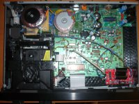
I've got a CD63 with a valve output stage (not my own work) which I've also since done some basic tweaks to, and I've done a LOT of reading of this thread and other helpful sources like Martin Clark's Acoustica.org.uk, Ray's PDF lists and Thorsten's info on the TNT site, but I'm no electronics expert...
Here's a quick pic from before I messed around with it...

I was really pleased with the sound of it generally, but there was an underlying interference noise I could hear when I played it at volume bothered me...
Here's a crappy video which shows the noise I was getting.
https://www.dropbox.com/s/lei5vyal70v6l8c/2013-02-05 11.36.05.mov
Because of the valve output stage, I'm not using anything after RO and LO from the DAC. But the valve stage mod left all the standard components in-tact with the exception of removing the RCA plugs on the back. I found that by cutting the pin 2 going to the 2 opamps Q605 Q606 in the output stage directly after where the RO and LO feeds were taken reduced the noise about half.

This took the edge off, but there was still a lot more hissssssssss than I'd like..
So I did a few basic mods and followed Martin Clark's guide to add some decoupling caps for the DAC, move the caps for the crystal and cut the track to sort the ground bounce and such. Very happy with the results
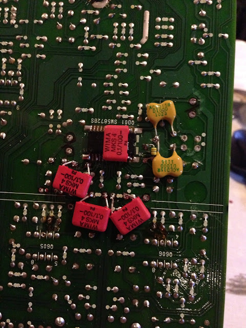
but he mentioned how a separate 5v feed to the DAC would help and after a helpful email or 2, I've added 3 new 5v feed to the DAC using 3 x simple 7805s for now. I also had a quick go at adding those tiny weeny decoupling caps directly to the DAC legs, but I fairly quickly chickened out of such a delicate job and added some 100nf WIMA film caps in the original ceramic locations instead. I also increased the electrolytic caps for the DAC 5v supplies and moved them closer into the ceramic locations too.
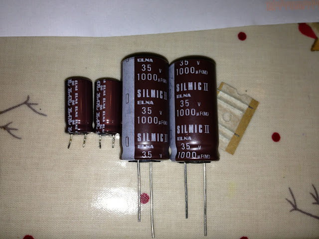
I beefed up the larger Power supply caps while I was there as this player's not even an SE, so some were tiny.
Here's a comparison of old and new C804 C805 caps..
Here's a quick couple of pics of where it stands now:

I'm very impressed with the results now, the detail and focus has really improved
Where am I going with all this?
well basically, I'm not interested in pushing this to the Nth degree or spending a huge load of time and cash, but I'm still getting an interference hissssssssssssss which can go almost undetected with quieter listening, but when I've got it cranked and I'm listening to something with a quiet, delicate section, is still quite pronounced. I'd be thrilled and consider this project complete to get those deep, dark silences rather than fuzzy grey ones and I'm convinced there's a few basic mods I can still do which will help.
My next round of mods is to change out the power supply diodes for Schottkey 11dq10, decouple some of the larger power supply caps with 100n PPS or XR7 as per Ray's list and maybe filtering the power input with a IEC socket and Choke and Cap.
But I can't help feeling that if a major problem with this player is an overloaded and noisy 5v+ circuit, that having a load of unused crap still connected can't be helping things....
Is there a simple way I can totally cut off the unused standard output stage/hdam and headphone output and such from the power supply so it's no longer connected? Can I just remove all the caps north of the DAC supplies or are there some jumpers I can cut?
I also have a couple of 7805 spare. Do you think I'd see any real gains from using these for the decoder?
Also, seems like a total newbie question, but what type of wire should I be using for connecting the input of these new regs to the 10v rail and are there any techniques I should be observing to limit interference here? I see a lot of twisted pairs with 1 end not connected in other people's pics?
cheers,
James
What a thread!
I've got a CD63 with a valve output stage (not my own work) which I've also since done some basic tweaks to, and I've done a LOT of reading of this thread and other helpful sources like Martin Clark's Acoustica.org.uk, Ray's PDF lists and Thorsten's info on the TNT site, but I'm no electronics expert...
Here's a quick pic from before I messed around with it...
I was really pleased with the sound of it generally, but there was an underlying interference noise I could hear when I played it at volume bothered me...
Here's a crappy video which shows the noise I was getting.
https://www.dropbox.com/s/lei5vyal70v6l8c/2013-02-05 11.36.05.mov
Because of the valve output stage, I'm not using anything after RO and LO from the DAC. But the valve stage mod left all the standard components in-tact with the exception of removing the RCA plugs on the back. I found that by cutting the pin 2 going to the 2 opamps Q605 Q606 in the output stage directly after where the RO and LO feeds were taken reduced the noise about half.
This took the edge off, but there was still a lot more hissssssssss than I'd like..
So I did a few basic mods and followed Martin Clark's guide to add some decoupling caps for the DAC, move the caps for the crystal and cut the track to sort the ground bounce and such. Very happy with the results
but he mentioned how a separate 5v feed to the DAC would help and after a helpful email or 2, I've added 3 new 5v feed to the DAC using 3 x simple 7805s for now. I also had a quick go at adding those tiny weeny decoupling caps directly to the DAC legs, but I fairly quickly chickened out of such a delicate job and added some 100nf WIMA film caps in the original ceramic locations instead. I also increased the electrolytic caps for the DAC 5v supplies and moved them closer into the ceramic locations too.
I beefed up the larger Power supply caps while I was there as this player's not even an SE, so some were tiny.
Here's a comparison of old and new C804 C805 caps..
Here's a quick couple of pics of where it stands now:
I'm very impressed with the results now, the detail and focus has really improved
Where am I going with all this?
well basically, I'm not interested in pushing this to the Nth degree or spending a huge load of time and cash, but I'm still getting an interference hissssssssssssss which can go almost undetected with quieter listening, but when I've got it cranked and I'm listening to something with a quiet, delicate section, is still quite pronounced. I'd be thrilled and consider this project complete to get those deep, dark silences rather than fuzzy grey ones and I'm convinced there's a few basic mods I can still do which will help.
My next round of mods is to change out the power supply diodes for Schottkey 11dq10, decouple some of the larger power supply caps with 100n PPS or XR7 as per Ray's list and maybe filtering the power input with a IEC socket and Choke and Cap.
But I can't help feeling that if a major problem with this player is an overloaded and noisy 5v+ circuit, that having a load of unused crap still connected can't be helping things....
Is there a simple way I can totally cut off the unused standard output stage/hdam and headphone output and such from the power supply so it's no longer connected? Can I just remove all the caps north of the DAC supplies or are there some jumpers I can cut?
I also have a couple of 7805 spare. Do you think I'd see any real gains from using these for the decoder?
Also, seems like a total newbie question, but what type of wire should I be using for connecting the input of these new regs to the 10v rail and are there any techniques I should be observing to limit interference here? I see a lot of twisted pairs with 1 end not connected in other people's pics?
cheers,
James
Lots of work gone on in there nice!
All the 5v feeds inc the decoder will benefit from separate regulation. I would feed the individual rails for it with separate regs. While you are doing that, you could also do the same for the HF amp
One of the issues is see is that the valve stage only uses half the output if the DAC. I don't think this is ideal! Maybe your hiss problem could be related to this in so far as the gain required is maybe a bit high. I've looked at those valve stages before and although I've not listened to one, I've no desire to play with one for that reason. I'll take Rays DOS (discrete output stage) over that valve stage all day.
Also, the caps you have changed in the power supply for the 1000uf silmics are doing nothing!!!!!!! The valve stage replaced the entire analogue output stage....those caps only supply the analogue output stage.
For now, I'd add some more regs and see what you think
Btw, quick win is to replace c813 with at least 10,000uF (I'd use 22,000uF) it very important. At the same time, wire out the 2 glass fuses
nice!All the 5v feeds inc the decoder will benefit from separate regulation. I would feed the individual rails for it with separate regs. While you are doing that, you could also do the same for the HF amp
One of the issues is see is that the valve stage only uses half the output if the DAC. I don't think this is ideal! Maybe your hiss problem could be related to this in so far as the gain required is maybe a bit high. I've looked at those valve stages before and although I've not listened to one, I've no desire to play with one for that reason. I'll take Rays DOS (discrete output stage) over that valve stage all day.
Also, the caps you have changed in the power supply for the 1000uf silmics are doing nothing!!!!!!! The valve stage replaced the entire analogue output stage....those caps only supply the analogue output stage.
For now, I'd add some more regs and see what you think
Btw, quick win is to replace c813 with at least 10,000uF (I'd use 22,000uF) it very important. At the same time, wire out the 2 glass fuses
Thanks for the input
I appreciate its never going to be the worlds best, but I really enjoy listening to it and I like the steampunk simplicity of the valve stage
Yeah the valve output stage is only using half the DAC output. I can see how more gain needed for a quieter signal could highlight the hiss where usually its not detectable so maybe it's here to stay...
I'll add a few more regs like you say and disable the power to the standard output and such and see where that leaves me.
Cheers for the heads up on the c804 c805 caps, lol. That kind of highlights where I'm at... It's hard to decider which mods are for what and which are applicable if my output stage is ignored. Does that also mean there's no point in me swapping out some of the Rectifier diodes?
How do people usually disable the standard output stage from the power circuit if they're using a DOS?
Also, out of interest, is the recommended chassis damping to reduce mechanical resonance or electrical interference? Or a bit of both?
Cheers,
James
Hi James those Green resistors (8 of them) between the op-amps and Hdam screen cans R613 R651 Etc. supply power to the output stages. There are also a couple of jumpers feeding these resistors I don't have the schematic for the 63 at hand but U223 and U224 look like the ones you need to snip. Check with your meter first!
Last edited:
Hi James those Green resistors (8 of them) between the op-amps and Hdam screen cans R613 R651 Etc. supply power to the output stages. There are also a couple of jumpers feeding these resistors I don't have the schematic for the 63 at hand but U223 and U224 look like the ones you need to snip. Check with your meter first!
Thanks
I've just gone over the schematics and from what I can work out, U216 gives +12v to the output stage inc headphones and U218 gives it -12v. But, remove those links and there's nothing at all attached to the 78m12 reg's output and almost nothing on the 79m12 (I can't work out what u227 leads to)
I can also see now how pointless upgrading the c803-c806 caps is on my machine.... Oh well, always learning
Hi
I have recently started modding my 15 year old KI mkII. I have replaced the RCA output sockets with gold-plated Neutriks. I removed the muting transistors and the dc blocking caps. Replaced C611-C614 with the Elna Silmics dc blocking caps I removed earlier. Wired from HDAM to the RCA sockets.
The DC offset I measure out of right channel is 7mv, but out of the left channel its 50mv. Im not worried about this, since my amp has dc blocking on input. What could be the reason for this difference of dc offset?
Short list for the CD63SE
Can anyone suggest the top 5 or 10 mods for the 63 SE? The ones that yield the most improvement for the effort/cost. I have already replaced the output RCA's with VdH's through necessity after 1 jack developed a intermittent connection. I have looked at the list on the first page and the TNT-audio site, but not sure where to start. (I promise to try someday to read through all 1910 pages of this thread)
Thanks!
Hi
The DC offset I measure out of right channel is 7mv, but out of the left channel its 50mv. Im not worried about this, since my amp has dc blocking on input. What could be the reason for this difference of dc offset?
Just component tolerance I guess.
Simon
Can anyone suggest the top 5 or 10 mods for the 63 SE?
Hmm, it's been a while but the TOP ones should include:
* servo re-clock
* DAC re-clock
* servo driver IC regulators (x6), preferably fed from their own transformer / PSU
* output op-amps
* DC blocking output caps bypass
Do these 5 and you will have a KILLER machine.
Simon
the same goes for the 67 MK2, right?
how actively answer is the coax mod and what should I do?
In the 67, Servo and DAC share the same clock.
Also in 67 servo drive is allready regulated if I recall correctly
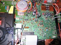
Thought I'd give an update on how my mods are progressing. It's slow going since I am still a newbie at this stuff (but learning), and I need help from a friend – Chris, registered on this site – who is very kindly giving me loads of assistance with this project, and checking voltages, etc. Also, many thanks to those on this site who have given lots of help.
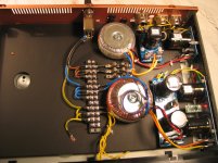
So far I have set up power supplies in a second box, another Marantz CD63SE, for the new DAC clock, servo clock and the power supply for the servo itself. These feed the original player via XLR sockets and separate interconnects. I have also bypassed the HDAM, fitted new opamps (LME49720HA), fitted new caps in this area, removed the muting circuit and disconnected the headphones.
I set up the clocks on Ray's flea boards, and mounted these in the player as daughter-boards, but used different components to Ray's. These daughter-boards are located near the original clocks.
I happen to have a very expensive Katana SACD player on loan from a friend at the mo. This player was not commercially available in its time but would have retailed at over £10K, and this was a good comparison for my new modded player. There was not a great deal in it, but the Katana just came out tops – not surprising given the price difference! I checked frequency extremes, and here neither came out on top (I thought the bass would have been tighter on the Kat, but not so.) The Kat has a slightly lower noise floor resulting in a smidgen more space round singers/instruments, and is a little sweeter-sounding in the mid than my Marantz. But all-in-all not a bad performance from the Marantz, especially since the components have not been given time yet to become fully optimised.
I thought I would tackle the power supply for the output stage next. What do those on here think: will this give me the next biggest improvement?
Attachments
Thought I'd give an update on how my mods are progressing. It's slow going since I am still a newbie at this stuff (but learning), and I need help from a friend – Chris, registered on this site – who is very kindly giving me loads of assistance with this project, and checking voltages, etc. Also, many thanks to those on this site who have given lots of help.
So far I have set up power supplies in a second box, another Marantz CD63SE, for the new DAC clock, servo clock and the power supply for the servo itself. These feed the original player via XLR sockets and separate interconnects. I have also bypassed the HDAM, fitted new opamps (LME49720HA), fitted new caps in this area, removed the muting circuit and disconnected the headphones.
I set up the clocks on Ray's flea boards, and mounted these in the player as daughter-boards, but used different components to Ray's. These daughter-boards are located near the original clocks.
I happen to have a very expensive Katana SACD player on loan from a friend at the mo. This player was not commercially available in its time but would have retailed at over £10K, and this was a good comparison for my new modded player. There was not a great deal in it, but the Katana just came out tops – not surprising given the price difference! I checked frequency extremes, and here neither came out on top (I thought the bass would have been tighter on the Kat, but not so.) The Kat has a slightly lower noise floor resulting in a smidgen more space round singers/instruments, and is a little sweeter-sounding in the mid than my Marantz. But all-in-all not a bad performance from the Marantz, especially since the components have not been given time yet to become fully optimised.
I thought I would tackle the power supply for the output stage next. What do those on here think: will this give me the next biggest improvement?
Good work. You have done most of the modding work. I would suggest you should change the 7812 and 7912 regulators for the analogue rail by two low noise voltage regulators of + and - 15V as it will perform better for the opamps (if your external psu have not done so). You may also try discrete opamps to replace your 49720HAs. At the same time feed independent low noise 5V regulated voltage to the servo, the decoder and the DAC. I noticed that you have not changed the filtering caps for the servo, DAC and decoders etc and these should also be changed. The last thing you could do is to consider inserting a relay operated muting circuit to get rid of the annoying cracking noise when switching off your CD63. Hope the above can help.
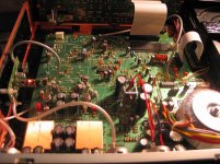
The following photos show two of the CD63s I have modded (see thread number 19021 and 19029):
http://www.diyaudio.com/forums/digital-source/54009-marantz-cd63-cd67-mods-list-1903.html
As to the SQ the modded CD63 beats my previously owned Leema Antila IIS costing more than 3000 pounds and as such I sold the Leema in the Bay.
Last edited:
"Good work. You have done most of the modding work. I would suggest you should change the 7812 and 7912 regulators for the analogue rail by two low noise voltage regulators of + and - 15V as it will perform better for the opamps (if your external psu have not done so). You may also try discrete opamps to replace your 49720HAs. At the same time feed independent low noise 5V regulated voltage to the servo, the decoder and the DAC. I noticed that you have not changed the filtering caps for the servo, DAC and decoders etc and these should also be changed. The last thing you could do is to consider inserting a relay operated muting circuit to get rid of the annoying cracking noise when switching off your CD63. Hope the above can help."
Hi Higlander,
Thanks for your comments. From your list, I have already regulated the power supply to the servo and DAC via a 5-Volt S-power regulated supply. The transformer, diodes, and smoothing caps (mounted on separate daughter boards in the 'power supply' case) feed DC to the 5-Volt regulator on the flea board (in the main player) which also carry the clocks. The clocks are hard-wired down to the board.
For the servo power supply, I have separate daughter boards (one + and one -) in the 'power supply' case each carrying diodes, smoothing cap, 12-Volt S-power regulator, further smoothing cap feeding the main player, again hard-wired down to the main board. Sorry for my ignorance, but does this mean I also have to "change the filtering caps for the servo, DAC and decoders etc"? Have I not done this already?
I have not done anything about the power supply for the output stage yet. When I set up a separate transformer, diodes, smoothing cap, s-power regulators, etc, will this make an appreciable difference?
Thanks again for your comments.
- Home
- Source & Line
- Digital Source
- Marantz CD63 & CD67 mods list