relay
Its not a problem to switch off the amp first, at the moment im
thinking of moving over to cfp dos over lme 49720ha/s anyway
thx alan")
Thx ray,Alan,
The relay contacts are not connected in series with the signal, so there's no loss involved. Instead, they connect the outputs to GND when muting is active. You have to connect two 47ohm resistors in series with the ouputs though, you can't short the outputs hard to GND directly. But this was already the case in the original player (2x 100 ohms in series).
Ray
Its not a problem to switch off the amp first, at the moment im
thinking of moving over to cfp dos over lme 49720ha/s anyway
thx alan
Hi, "bonne annéeeeeeeee"
Don't know if somebody try supercap as a battery before very low ESR cap like OSCON as supply before a DAC ?
It's hard to read every posts here from the beginning. I plan to feed a TDA1545a like that (Philips cd723) : main powersupply -> 4700 uf standard ca -> 0r7 -> 7805 reg with diode to adj (5,6 v) - 100 nf platic cap -> 0Rr5 (to make resistive output=passive supply) ->1500 uf (not low esr because better for sound after this type of reg; 1500 to flat impedance curve) -> SuperCap 0,5 F ( ripple killer? & as a batery) -> 0,1 uH Neosid -> smd very low esr cap (smd Panasonic SEPC : hope to be as good as larger SEPC Sanyo can type?) at the pins of the TDA 1545a... perhaps with 100 nf smd ceramic (or 10 nf ?)
Is it good, has it sense to make passive with active like simple 78xx reg ? I saw in a old CD42 (tda1540d) I have that Marantz use two normal 79xx in cascad to feed the tda540 and here all the caps value are small : 370 uf first then around 220 uf between the reg if my memory is not bad !
In fact I don't understand if these DAC need to see a linear voltage or better a stable curent and of course if caps be better than active stage for that (I don't spak about the continuous calibration Ir stage of the TDA1545a here)
Thank you in advance if someone has experiment a simple solution here because I' not a technician and d'ont want to go to a very or to pricy active stage to feed the DAC chip.
Eldam
I have 22,000uF -> LM317 -> BG NX/FK on each of my DAC pins, so 88,000uF total capacitance pre-reg. I think this is overkill. The DAC stays powered for about a minute after powering down. I think separate supplies are worthwhile but not so much capacitance is required.
I have 22,000uF -> LM317 -> BG NX/FK on each of my DAC pins, so 88,000uF total capacitance pre-reg. I think this is overkill. The DAC stays powered for about a minute after powering down. I think separate supplies are worthwhile but not so much capacitance is required.
Hi, thanks for your reply,
What type of cap for the 22k uF ? Is the LM used for anothers active stage or only for the Dac chip ? In my Philips Cd723 the reg is not only used for the DAC that why i want to isolate the dac from the transformer with this Supercap as a battery, the personal cap for the DAC will be a low ESR like you. For what i Understand it's not the same if reg is only use for DAC or share its work with another circuit with the DAC..
I have just two 33 uf BG NX but sound harder IMHO than Sanyo OS-CON FS series for DACs (with TDA1545a & TDA1543).
Do you benchmark with big cap after you LM317 ? they seem (LM even L type) sound better if a "high" ESR cap is used at the output pin.
Do you try for example : big cap (low esr if not just after transformer) -> LM317 -> small cap (47 to 200 uf) or big cap (two are normal caps with high ESR) on LM pins -> BG NX/FX on DAC pins ?
I read that at the output of old regulators with modern caps (even of low grade) it's better if you use a little resistor (0R2 ?) in serie between the pin cap and ground (=the regs sounded better with old caps with high ESR, which I agree after hear tests on old Philips players : nichicon or philips caps).
Last edited:
Each DAC pin has its own dedicated transformer secondaries and diode bridge. DC is filtered by 22,000uF Mundorf AG. That feeds an LM317 board as per Martin Clark's tutorial 'Using 3-pin regulators off-piste' on Acoustica (sorry no link - replying from phone). They have small tantalum caps at the pins and green LEDs to set voltage. The regulated voltage is then fed direct to pin with BG 470uF local decoupling, NX series for digital and FK for analogue.
0,22 F for one rail and the little curent needs for the DAC, I can understand that you don't need Pi filter before your DAC...
Have to googling about Martin Clark's tutorial 'Using 3-pin regulators off-piste' on Acoustica.
I used to work with Philips Co136 or panasonic FM and basic nichicon but I have to try these Mundorf cap,
thank you Ben,
Anybody else please about gold cap / super cap emulating battery supply for low curent active device like DAC ? I don't find explicite answer here, or how to work with small inductance like neosid.
I'm looking for a small tweak here with caps and resistor... maybe small inductor (not a standalone transformer for DAC like Ben)
kind regards
Eldam
Have to googling about Martin Clark's tutorial 'Using 3-pin regulators off-piste' on Acoustica.
I used to work with Philips Co136 or panasonic FM and basic nichicon but I have to try these Mundorf cap,
thank you Ben,
Anybody else please about gold cap / super cap emulating battery supply for low curent active device like DAC ? I don't find
explicite answer here, or how to work with small inductance like neosid.I'm looking for a small tweak here with caps and resistor... maybe small inductor (not a standalone transformer for DAC like Ben)
kind regards
Eldam
You can do the 63 without regulating and/or with regulating the servo driver psu, of course regualiting improves further. The one thing that needs sorting regardless is the psu. Disconnecting the tx for the +/- 10V is required and fit in the player a 2x 12V 30va - 50va tx to supply these rails. It makes a massive improvement. You can then run the regs at +/- 12V dc
Brent
Hi there, Brent or anyone, wich are the 3 pins for the 10V rails? I do have a TX to connect in there... U308 and U310? Need to keep u309 in and connect my new TX ground with the existing ground?
Thanks!
Last edited:
Hi Matthieu,
Yes, you have to make three connections to the board, U309 goes to the center tap of the new tranny, that is formed by connecting the two new windings in series. But I would use the ground point at U274 instead, this keeps the current path short.
Beware to keep the original tranny connected though, there's an extra 13.9V that runs to C854 for the display voltage, and it's used as power-on voltage through DN01...04. So you'll have to cut tracks somewhere between the fuses and D811...814 if you want to leave that intact, or take these four diodes out and fit an off-board rectifier somewhere.
If you don't mind that the new tranny feeds this extra stuff (I don't think it will do much harm), the easiest way to connect it is by taking out the fuses and use that as an insertion point. But I'd recommend to put some new fuses in... If one of the driver IC's ever burns out, a 50VA tranny can create a lot of damage!
Regards,
Ray
The player is owned by... my boss!
Don't want to be fired
Hi Malefoda
if i was you, i will wait until someone attach picture
im not expert
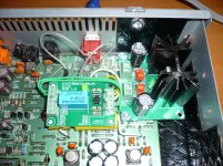
@RAY: I have installed a relay operated muting circuit according to your advise and it works like a charm. Now there is no cracking annoying noise when switching off the CD63.I see what you mean, but your drawing is correct. The decoder will pull down the voltage through the diodes, so it controls the voltage at that point and thereby the muting. POWM provides voltage, but through the 47k resistor. So the moment the decoder starts pulling current through the diode, this voltage drops fast to around 0.6V. You may have to lower RN31 to 1k to get it working properly.
Ray
Thank you very much.Initially I used a 47 ohm resistor to connect the RCA output to ground on each channel when the CDP is not playing but it did not eliminate the cracking noise on switching off the player. Eventually I remove the resistor and connect the RCA output to ground directly through the NC relay and it worked. I hope this arrangement will not cause any harm to the opamps as I have a 4.7uF muting capacitor connected between the RCA output and the opamp.
As a matter of interest on the top right hand corner in the photo there is a low noise voltage regulator using LT1764 which I use to replace the stock 7805 regulator supplying +5V to the circuits.
Attachments
Last edited:
I bought it from the eBay which is sent from Hong Kong:I want to do this. Is that one of those eBay boards? I tried to buy one but he won't ship to Canada. I expect I'll end up building one on veroboard instead.
DPDT Signal Relay Module, 5Vdc, TAKAMISAWA RY5W-K Relay. Has Assembled. | eBay
I used a 5V relay instead of a 12V one. It depends where you want to tap the source out.
It took ages (about 2-3 weeks) to arrive the UK and I think they will ship it to Canada. It is well packaged, nicely made, handy and cheap - excellent product. It should be cheaper than making one yourself
Initially I used a 47 ohm resistor to connect the RCA output to ground on each channel when the CDP is not playing but it did not eliminate the cracking noise on switching off the player. Eventually I remove the resistor and connect the RCA output to ground directly through the NC relay and it worked. I hope this arrangement will not cause any harm to the opamps as I have a 4.7uF muting capacitor connected between the RCA output and the opamp.
I think I found what had come wrong
. I connected the 47R to the RCA output and then ground it by the NC contact of the relay which I think is wrong (in this case the RCA still has output signal and the 47R only ground a bit of the signal). What I should do is to put a 47R in series between the 4.7uF isolating cap and the RCA output and the NC contact should connect to the RCA output after the 47R and to ground. When the NC contact is closed then the output signal is completely short to ground. I will modify the circuit when I have the time.As a matter of interest, if I don't have the 47R and short the output directly to ground what will be the effect on the circuit ?I was just about to post that, but you already figured it out
- Home
- Source & Line
- Digital Source
- Marantz CD63 & CD67 mods list