Muting circuit
@Ray and Happy New Year to all. From your web I noticed that you have suggested using a relay for the muting circuit and provided with a circuit diagram. However I found the following finished product in the fleabay:
DPDT Signal Relay Module 12Vdc TAKAMISAWA RY12W-K Relay - UK SELLER - #885 | eBay
For the 12V power supply to the relay I can tap it out from resistor RN08 after DN01 and DN02. As to the muting control signal shall I just feed the signal from the collector of either QN24 or QN25 to the input of the fleabay's relay unit ?
Happy new year! 
Good to hear your player is singing again!
That's a handy little PCB
You have to wire it in such way that the normally closed contacts are connected between audio-signal and GND. So that in power-less condition, the relay is inactive and signal is muted. This will take away all the switch on/off noises.
The original muting transistors work in an opposite way as the relay: they are active when the signal needs to be muted and LMUT and RMUT lines are high (+5V). So you need that signal inverted. You can do that by taking QN24 or QN25 out and connect directly to the decoder. The base of QN24/25 is the point where you can connect the input of the muting PCB. You may have to lower RN30/31 to 1k to get it to work.
Regards,
Ray
Thanks Ray. If I don't want to touch QN24/25 do you think the muting can work when I connect the audio signal and ground to the Normal Open contacts of the relay?Happy new year!
Good to hear your player is singing again!
That's a handy little PCB
You have to wire it in such way that the normally closed contacts are connected between audio-signal and GND. So that in power-less condition, the relay is inactive and signal is muted. This will take away all the switch on/off noises.
The original muting transistors work in an opposite way as the relay: they are active when the signal needs to be muted and LMUT and RMUT lines are high (+5V). So you need that signal inverted. You can do that by taking QN24 or QN25 out and connect directly to the decoder. The base of QN24/25 is the point where you can connect the input of the muting PCB. You may have to lower RN30/31 to 1k to get it to work.
Regards,
Ray
Thanks Ray. If I don't want to touch QN24/25 do you think the muting can work when I connect the audio signal and ground to the Normal Open contacts of the relay?
OH, I don't think connecting the NO contact of the relay will work. When there is no power the audio signal will go through the RCA output directly and not goes to ground. My mistake.
@Ray can you advise if the connection in the uploaded diagram is correct. The control of the relay needs 5V signal but it seems that the signal from the decoder is 0V but the POWM always provide a 4.5V before RN31 which in this case will always activate the muting relay. It seems to me it is not right.
Attachments
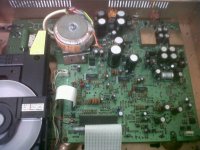
Is that picture your player? If so you have completely bypassed the HDAM and linked the output stage output direct to the output. If the output phonos are still connected to the PCB, you will still have the muting transistors in circuit and by linking those caps out will be feeding the sound into the output of the HDAM??
turns to Having seen the picture in post 18938 it reminded me somewhat (well exactly actually!) of my modded player
Today I remedied the situation and put some additional phono sockets on the back the panel and re-routed the signal out. Well.....now I know what all the fuss is about. I have done major mods to this player as have most others on here. However I was not that impressed with the sound and still thought it a bit uncouth and "shouty". Not any more. What a transformation. I don't have to give details as you will all already know.
Rob.
@Ray can you advise if the connection in the uploaded diagram is correct. The control of the relay needs 5V signal but it seems that the signal from the decoder is 0V but the POWM always provide a 4.5V before RN31 which in this case will always activate the muting relay. It seems to me it is not right.
I see what you mean, but your drawing is correct. The decoder will pull down the voltage through the diodes, so it controls the voltage at that point and thereby the muting. POWM provides voltage, but through the 47k resistor. So the moment the decoder starts pulling current through the diode, this voltage drops fast to around 0.6V. You may have to lower RN31 to 1k to get it working properly.
Ray
...What a transformation...
Rob.
That must have been quite a 'Eureka'-moment
I see what you mean, but your drawing is correct. The decoder will pull down the voltage through the diodes, so it controls the voltage at that point and thereby the muting. POWM provides voltage, but through the 47k resistor. So the moment the decoder starts pulling current through the diode, this voltage drops fast to around 0.6V. You may have to lower RN31 to 1k to get it working properly.
Ray
Thanks Ray for confirming that my drawing is correct and I will based on this to insert a muting circuit in my 63SE which I am working on now. Now I understand how the muting circuit works and thanks again for your advise.
That must have been quite a 'Eureka'-moment
Ohhh Yess. A Happy New Year to Meeeeee.
HNY
Same
Anyway,
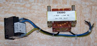
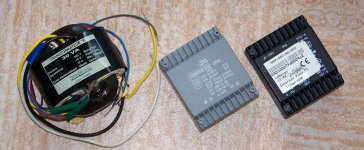
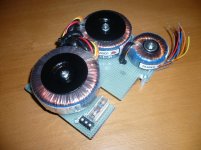
I can save some discarded stuff at my job, like thousand film caps, some FCs, PSUs and enclosures.
I wonder if these can be usefull for the CD-43 ; the TXs will do fine, just wonder how to fit them in, maybe they'll go external if I can't fit them in. It can also be great as I can smooth then with hundreds of standard 1000µF Panasonic
Filter (from telecom gears) may or not... was used in front of a SMPS, maybe to avoid noise back on mains? Then better used before my Tripath SMPS...
Again, HNY!
Same
Anyway,
I can save some discarded stuff at my job, like thousand film caps, some FCs, PSUs and enclosures.
I wonder if these can be usefull for the CD-43 ; the TXs will do fine, just wonder how to fit them in, maybe they'll go external if I can't fit them in. It can also be great as I can smooth then with hundreds of standard 1000µF Panasonic
Filter (from telecom gears) may or not... was used in front of a SMPS, maybe to avoid noise back on mains? Then better used before my Tripath SMPS...
Again, HNY!
Attachments
Is that picture your player? If so you have completely bypassed the HDAM and linked the output stage output direct to the output. If the output phonos are still connected to the PCB, you will still have the muting transistors in circuit and by linking those caps out will be feeding the sound into the output of the HDAM??
Std is
Dac > Opamp and filter > HDAM > DC blocking caps (silmics) > muting > phono sockets
Ideally you want
Dac > Opamp and filter > phono sockets
It looks like you have achieved a quite remarkable hybrid that I've never seen previously
DAC > opamp and filter > phono sockets > muting > links where the DC blocking caps were > HDAM (backwards and without power)
Either fit new sockets directly on the end of the output from the Opamp and filter section or removed the components that are now feeding the audio backwards into the muting stage, linked out caps and Dead HDAM!
Grab the manual and work out the signal path!!
Hi UV101
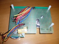
those picture was SimontY picture from page 11 post # 115
this picture above is taken from last mods from my cd
i desolder those caps, now is looks like freeway
after the laser just read a view cd so i change the laser
but looks like the white gear have some damage there
so i will wait for a new mechanical laser for my CD63KI
just go back from AD 823 to JRC 2114
OP 270 AZ and LM 6172 IN are waiting
Happy new year everyone
Best regards
Attachments
Hi all ,
Happy new year just fitted a cheap clock to one of my 63s great sound but an annoying sound at switch off. needs a relay or muting ,n
cheers alan.
I have the same problem as yours and is considering fitting this :
DPDT Signal Relay Module 12Vdc TAKAMISAWA RY12W-K Relay - UK SELLER - #885 | eBay
HI,I have the same problem as yours and is considering fitting this :
DPDT Signal Relay Module 12Vdc TAKAMISAWA RY12W-K Relay - UK SELLER - #885 | eBay
By bypassing hdam and removing muting trannies and blocking caps causes this problem,But want to keep the less is more aproach in the signal path.
May have to live with it and switch amp off first.
Also ran the opamps and servo from a car battery amazing results.
cheers alan
Alan,
The relay contacts are not connected in series with the signal, so there's no loss involved. Instead, they connect the outputs to GND when muting is active. You have to connect two 47ohm resistors in series with the ouputs though, you can't short the outputs hard to GND directly. But this was already the case in the original player (2x 100 ohms in series).
Ray
- Home
- Source & Line
- Digital Source
- Marantz CD63 & CD67 mods list