Why buy an overpriced KI on eBay????? I can sell you a badge for £80 if you like!!!!! Thats terrible advise!!
That 67 is more than capable of equalling most DIY 63's if it get tidied up. Would you buy a new car because it needed a new tyre?
Get the main smothers back where they belong, get a large cap in the servo psu and swap the local caps as described a million times before......solid polymer on digital rails and Rubycon ZLh on analogue rails!
The only reason for going 63 over 67 is if you plan to run 2 clocks and use multiple discrete regs! Out the box the 67 out performs the 63 as its servo driver is regulated.
No point in buying a KI unless you want the badge, an SE is the same chassis just not copper plated (copper does look nice tho lmao!!) and the KI has a bigger toroidal transformer. By the time you've done the 1st round of mods, there's nothing in it!!!! In fact, you'd remove th better caps in the KI to replace with something 'better'!!
I'm also interested how Ben should use the scope to track down his mains hum???")
What about the external power supply. Shall i keep that for now
I'm also interested how Ben should use the scope to track down his mains hum???
Well, I haven't used one before but I can only measure voltage on my DMM at the moment; I can't see noise / voltage over time. If I can see 60Hz noise spikes on the analogue rails, for example, then that should help me narrow it down a bit, right?
Ben, did you mention that initially there was no hum but the hum developed sometime at a later stage. Can you recall what had you done to the circuit ?Well, I haven't used one before but I can only measure voltage on my DMM at the moment; I can't see noise / voltage over time. If I can see 60Hz noise spikes on the analogue rails, for example, then that should help me narrow it down a bit, right?
What about the external power supply. Shall i keep that for now
What is the psu? That area needs approx +/-15 v if you are using a single supply from a single 13.4v CB radio psu its not going to work correctly. Can you describe the psu and connectivity. Apologies if I missed this info in a previous post.
Don't worry we will help you get this sorted.
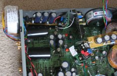
Btw Panasonic tsup 6800uf will fit in the original position in a 67.
In this pic you can see the big caps for the analogue rails in the original position along with the big 22,000uf cap on short leads on its side for the servo psu. This is one I did for a friend and its been back to me twice for additional work!!! It's quite significant now that's for sure!!!!

Well, I haven't used one before but I can only measure voltage on my DMM at the moment; I can't see noise / voltage over time. If I can see 60Hz noise spikes on the analogue rails, for example, then that should help me narrow it down a bit, right?
Brent has commented a couple of times on this. He suggested that he had similar problems which turned out to be location of psu components and cabling. Check back through the last few posts.
Other wise you will need to start back tracking through your psu mods to see which rail is upsetting it.
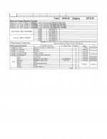
Current Power Supply Design
Here is my current design:
-50VA Tx's outside the case, 25VA Tx's inside the case
-RCRCRC filters
-SupperTeddy/Audio-gd Super Regs
You should be able to get 6 PS into the case (this will require several redesigns/repsitioning of the voltage regulators, very tedious).
- 50VA to the clocks
- 50VA to the OpAmps
- 50VA to the Laser (+- 10 VDC)
- 3 X 25 VA to the 5 VDC rails
Also, the cost add up fast. Even using chinese parts and bare pcb's, my final cost will be close to $1000.00 (without shipping).
Attachments
Here is my current design:
-50VA Tx's outside the case, 25VA Tx's inside the case
-RCRCRC filters
-SupperTeddy/Audio-gd Super Regs
You should be able to get 6 PS into the case (this will require several redesigns/repsitioning of the voltage regulators, very tedious).
- 50VA to the clocks
- 50VA to the OpAmps
- 50VA to the Laser (+- 10 VDC)
- 3 X 25 VA to the 5 VDC rails
Also, the cost add up fast. Even using chinese parts and bare pcb's, my final cost will be close to $1000.00 (without shipping).
I dont think i could do that i can change caps and stuff like that but that looks too difficult for me. Im better at makeing speaker cabinets and things like that
Brent has commented a couple of times on this. He suggested that he had similar problems which turned out to be location of psu components and cabling. Check back through the last few posts.
Other wise you will need to start back tracking through your psu mods to see which rail is upsetting it.
Thanks for your help, Brent and Ian,
Sorry, couple of conversations going in parallel here. I already started the process of backtracking but it's not easy when my player breaks for some other reason every time I take the board out. All of my PSUs are at least as far away from diodes/regs as the stock tx, but there is definitely a lot more wiring in that area behind the CD tray. I'll consider building an external output stage PSU to clear things up a bit.
Beautiful work in that last pic, Ian. It makes me want to start again.
Thanks Ben. I'm sure you can imagine, it's taken some practice.
I have at least 4 totally dead players due to knackered tracks or dead chips. I've just counted 11 63's and 3 67's that have passed through my hands in 4 years! Still got 4 63's that need to get a bit sorted and sold. I guess practice makes ....well at least you get better!!!
I have at least 4 totally dead players due to knackered tracks or dead chips. I've just counted 11 63's and 3 67's that have passed through my hands in 4 years! Still got 4 63's that need to get a bit sorted and sold. I guess practice makes ....well at least you get better!!!
Here is my current design:
-50VA Tx's outside the case, 25VA Tx's inside the case
-RCRCRC filters
-SupperTeddy/Audio-gd Super Regs
You should be able to get 6 PS into the case (this will require several redesigns/repsitioning of the voltage regulators, very tedious).
- 50VA to the clocks
- 50VA to the OpAmps
- 50VA to the Laser (+- 10 VDC)
- 3 X 25 VA to the 5 VDC rails
Also, the cost add up fast. Even using chinese parts and bare pcb's, my final cost will be close to $1000.00 (without shipping).
Not sure that lot should add up to $1000 but it depends on the clocks and regs you are using.
Looking at the mods you have, you don't need the output caps as there should not be any DC present on the output. Also, personally, I don't like FC caps after the regs. They are great pre reg, but I prefer to use Rubycon ZLG on analogue rails and definitely no question about using anything others than solid polymer on digital rails.
What size cap do you have for the main pre 5v reg smoother. It's important to use a very high value on that rail. Also, have you regulated the servo supply because that is definitely worth doing too.
Thanks Ben. I'm sure you can imagine, it's taken some practice.
I have at least 4 totally dead players due to knackered tracks or dead chips. I've just counted 11 63's and 3 67's that have passed through my hands in 4 years! Still got 4 63's that need to get a bit sorted and sold. I guess practice makes ....well at least you get better!!!
A numebr of my friends having listened to my modded CD63 (not MKII SI) they were so much impressed by it had requested me to carry out similar work for them. So far I have already promised three of my friends to do the job but on the condition that they have the patient to wait for months as I will carry out the modding when I have no other things to do. Don't be mistaken I will only charge them on material costs and I am not doing this work for my living. Carrying out the work on 3 units I think will keep me busy for a few months

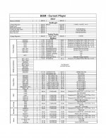
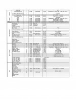
caps
rubycon 16v 470uf for opamps mundorf or tsups cheaper 22,000uf for psu
Could someone tell best caps for the opamps and and main power supply value as well
rubycon 16v 470uf for opamps mundorf or tsups cheaper 22,000uf for psu
Last edited:
rubycon 16v 470uf for opamps mundorf or tsups cheaper 22,000uf for psu
Thanks mate i will get them done then back for help
What voltage for psuThanks mate i will get them done then back for help
If you are getting the mundorfs they will be 25v but the Panasonic tsup's will be 16v.
I prefer the mundorfs but the tsup's are great value for money.
The caps after regs should not be FC's. I use a mix of BG and oscon sepc in my own player but favour Rubycon ZLG 470uF on analogue and Nichicon 330uF solid aluminium where budget is an issue. I also use large value Rubycon ZL or ZLH (1800uF) for the big cap after the main 5v reg.
There are arguments for smaller values for local decoupling, but interestingly, if you look at meridian kit, the prefer larger value local decoupling caps often using multiple 1000uf caps post reg with 470uf close to supply pins ( definately true in the 200 series equipment)
- Home
- Source & Line
- Digital Source
- Marantz CD63 & CD67 mods list