Hi Ray
You can use 4 regs on the dac. Left and Right for the analogue
Brent
You're right!

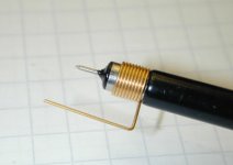
This is the famous Acoustica Clock Hack
The regulator is inserted where the 4.7 ohm safety resistor used to be. You can recognize them on the board: they are mounted 'in the air', at some distance from the board. Most chips have such a resistor in series with the supply-line. So it's very easy to separate parts of the circuit from the main supply: by removing the resistor, the section behind it is cut from the main 5V power. And it creates a perfect insertion-point for a new regulator to be added. This is where the output goes.
The new regulator can be powered from a new external supply, but you can also use the supply from the player. In the CD 63, all 5V comes from Q811, and this regulator is fed from C813. This is the point where you can hook-up the input of the new reg (the positive terminal that is). The GND terminal goes to the board's ground-plane on top.
Ray
Thanks Ray, will do this in the near future.
Hi Ray
You can use 4 regs on the dac. Left and Right for the analogue
Brent
So 4 would be AVDD1,2,3,4 and Grd to AVSS1 or any part of the ground plane?
Rob.
No, that would be 4 regs in total: two for DVDD and XVDD, one for AVDD1 and AVDD2 (this is the left channel) and one for AVDD3 and AVDD4 (right channel). GND goes to AVSS indeed.
Ray
Thank you, Ray, for taking the time to help us out.
The beauty of DIY.... 4 Regs for 1 IC. Mad but not beyond my imagination to do such a thing.
Was thinking of using LM317 tracking pre regulators with an LC filter at the input. The only down side of this is that I can't seem to get the design smaller than 70mm x 50mm. These PCBs each have their own on board rectifiers and associated smoothing capacitors. This is done with a view to possibly running individual transformers for some of the ICs in the future.
I would use S power regs or something similar if I could afford it. The LM317 regs above seem to simulate nicely in LTSpice and they are cheap to make. But are they a good idea sonically or would a straight basic LM317 be just as good.
As a side point I have been working through the mod list and have got as for as the CPU. The strange thing is that the IR only works if the remote is about 2 inches from the player. The remote is fine as the reference unmodded CD72 responds fine to the same remote. Is this normal or have I messed something up.
Its been educational doing this project. How each mod has affected the sound. Removing all the excess output circuitry and Op Amp upgrade made the sound much cleaner but the sound stage went to the dogs. Adding the Kwak clock sharpened things up and improved clarity but the sound went a bit harsh. The DAC changes made things even clearer but edgy. Then doing the decoder smoothed things out again.
I had no idea how a CD player worked before any of this. I'm having fun though. Makes a change to making amps and speakers.
No, that would be 4 regs in total: two for DVDD and XVDD, one for AVDD1 and AVDD2 (this is the left channel) and one for AVDD3 and AVDD4 (right channel). GND goes to AVSS indeed.
Ray
Cheers
You're welcome
The LM317 is a nice regulator, PSRR is good but the output noise is not that low unfortunately. For some applications this doesn't matter (like noisy digital stuff), and the LM317 can very well be used as a local regulator to separate circuits. Did you have a look at Acoustica's article? The gyrator is a good stage to put before any reg, even better than a passive LC filter.
If the boards are getting too big, why don't you fit the main caps and rectifier somewhere else?
I bet you replaced RY11 with an inductor. The remote problem can be solved by placing a 10...22uF cap across CY01 on the front panel PCB. Should add this to the mods list...
Ray
Ray,
Have read the article and added the gyrator to the front end of my regulators. It simulates ok. Gives -94dB @ 19.4 MHz. One thing that I'm trying to get my head around is that I thought that the purpose of adding regulators was to isolate that particular IC from the noise generated by the rest of the player. If the Lm317 isn't low noise doesn't that defeat the purpose of adding the regulators?
As for the remote problem, you are correct. And it does detail that cap on the mods list. Just me being a bit slow didn't add it cause I couldn't find it on the main PCB and didn't consider lookin at the display PCB. The display PCB to me is just an annoying ribbon cable that I'm expecting to fail at any time. I will be adding that cap very soon.
One thing that is bothering me is that while the player sounds so much better now there is something strange going on. Any one who listens to it complains about their ears getting a tight feeling. I too have noticed this too. I was wondering whether there is an oscillation problem somewhere in the player?
Many thanks for your help.
Paul
Hi Paul,
An extra regulator separates a section of the electronic circuit from the rest. It's not just the noise coming in that is attenuated, but it also reduces the effect of noise coming out of that piece of circuit. So it works in two directions. The LM317 is not particulary low-noise, but as long as the noise is less than before the regulator is added, the result is positive.
The tight feeling in your ears can indeed be caused by high-frequency oscillation. That would be the case if the player outputs a continuous HF tone that causes sound pressure. The only way to find out is by measuring with an oscilloscope. It could be the opamps, but then the effect will also occur if you are not playing a disc.
Ray
Am I wasting my time with the LM317? Is there a better alternative without spending silly money?
I am equiped with a scope. Can't do any form of audio elctronics without one. Would it be a case of monitoring the CD player outputs and hitting auto range? What sort of signal am I likely to be looking for? Op amps appear to be favourite as I would have thought that the output filters would remove any high frequency oscillation created further up stream. The tightness only started after doing the PSU mods as per sheet, so I suppose, a power rail check is in order...
I am equiped with a scope. Can't do any form of audio elctronics without one. Would it be a case of monitoring the CD player outputs and hitting auto range? What sort of signal am I likely to be looking for? Op amps appear to be favourite as I would have thought that the output filters would remove any high frequency oscillation created further up stream. The tightness only started after doing the PSU mods as per sheet, so I suppose, a power rail check is in order...
No, you are not wasting your time:
Just connect the scope to the analog outputs. If it's oscillating you'll see a sine wave of some sort appear >10kHz. It's best to check the power rails as well, some regulators start to oscillate with large caps on the output.
Ray
as long as the noise is less than before the regulator is added, the result is positive.
Just connect the scope to the analog outputs. If it's oscillating you'll see a sine wave of some sort appear >10kHz. It's best to check the power rails as well, some regulators start to oscillate with large caps on the output.
Ray
I think I may have an oscillation problem on the power rails. Specifically the 5V one supplied by Q871.
The noise at the inputs to the regulators is approx 10mV. The outputs of the regulators are as follows.
Q801/Q802 is approx 60mV noise with the scope reckoning the frequency is varying between 20Khz and 40Khz. Not sure about the accuracy of that but can see the waveform has a consistent period. The peaks on the wave vary a lot.
Q871 is approx 60mV noise at approx 20Khz. Similar waveform as above.
Q811 is approx 20mV noise at approx 40KHz. Similar waveform as before.
Even the analogue outputs have about 50mV of high frequency (>20KHz) noise on them.
Also, the 5V regulators are getting warm. I don't know if this is normal or not.
What do people reckon? Are the power rails in the CD67 inherently noisey anyway and what I'm seeing is normal?
Another question when the DAC is not processing information are the ouputs still actively changing state or do they go quiet?
This where one has to understand how the player works in greater depth.
I doubt that all regulators are oscillating, it's very unlikely. I'd rather think something is wrong with the ground that you chose for the scope probe. You are measuring with a probe, right? But it could be possible. What exact type regulators are you using, or are they still original?
The DAC inputs and outputs are always active. If there is no audio, the data to the DAC is simply '00000000' (well, sort of) and the outputs will show a 50% duty cycle square wave.
Ray
The DAC inputs and outputs are always active. If there is no audio, the data to the DAC is simply '00000000' (well, sort of) and the outputs will show a 50% duty cycle square wave.
Ray
I was using a scope probe and was grounded to the outsides of the Analogue output connectors. I thought that this would be good reference point as this the point where the CD player is referenced to the amplifier.
The regulators are still the originals. I didn't do the upgrades suggested as I wanted to add my own LM317/LT317 regs at a later date.
PSU rails seem very noisey after the regs. I was seeing peaks of over 100mV. The unregulated rails seemed posiotively quiet compared to the regulated rails. This noise seems to be transferring to the analogue outputs and I reckon that this is what is causing the listening "fatigue".
Is my choice of grounding point sound or is there a better place?
The problem with measuring noise like this is that the scope probe also picks up all the stuff that enters in the loop of the probe ground wire. See it as an inductor with one winding that acts as an antenna for radiated noise.
You can do a little test by connecting the probe ground wire to the outside of the analog connector again, and then connect the probe tip to another ground point, like U217 for example. I bet you will see lots of stuff on the screen already, even though you're measuring between GND's.
If you want to measure the noise only from the regulator, you need to connect the scope probe close to the output and GND pins of the regulator. A probe with a ground-spring is used for that. The spring minimises the loop-area.
I don't think the regulators are oscillating, this generally happens at much higher frequencies and with larger amplitude. You'll notice it easily on the scope screen when you see it.
Attachments
This is the famous Acoustica Clock Hack
The regulator is inserted where the 4.7 ohm safety resistor used to be. You can recognize them on the board: they are mounted 'in the air', at some distance from the board. Most chips have such a resistor in series with the supply-line. So it's very easy to separate parts of the circuit from the main supply: by removing the resistor, the section behind it is cut from the main 5V power. And it creates a perfect insertion-point for a new regulator to be added. This is where the output goes.
The new regulator can be powered from a new external supply, but you can also use the supply from the player. In the CD 63, all 5V comes from Q811, and this regulator is fed from C813. This is the point where you can hook-up the input of the new reg (the positive terminal that is). The GND terminal goes to the board's ground-plane on top.
Ray
Did this mod today and have it running on repeat for a couple of hours before critical listening. Am I right to assume that the 12v is taken from one side of the resistor? I have run a separate feed from the OUT of the 12v reg to the new 5v reg. This may not be necessary?
Am I right in thinking that 5v regs could replace all the 4.7k resistors?
Rob.
Hi Rob,
Which resistor would that be, the original 4.7 ohm? The regulators are fed from C813, do not use the analog +12V that's present in the player!
Ray
Ahh, I seem to remember you told me that.....and I ignored it!
Will change it. What about the other 4.7k resistors?
Rob.
Yes, you even quoted it...
Never mind, just use C813 as the supply-point for any 5V reg you want to add. All the 4.7 ohm resistors can be replaced, but the interesting ones are around the DAC, decoder and servo chip. But make sure to check the 5V output voltage is correct before you insert an LM317, to avoid smoked chips...
Oh, and leave R136 in place, it's for the laser!
Ray
- Home
- Source & Line
- Digital Source
- Marantz CD63 & CD67 mods list