Hi! I'm new on this forum and I have a question concerning the cd 43/CD53.
What can I do to delete the mechanical noise(like fffffffff) when the CD is rotating ? Because when listening at low level, I can ear my cd rotate ! I have the same pb on my 2 player (cd 43 and 53).
Thanks in advance for your answer.
Best regards
What can I do to delete the mechanical noise(like fffffffff) when the CD is rotating ? Because when listening at low level, I can ear my cd rotate ! I have the same pb on my 2 player (cd 43 and 53).
Thanks in advance for your answer.
Best regards
Is my C1 dead?
When reassembling my machine I must have pulled out the ground wire from my C1, have since reattached it and the player will not spin a disk. There is 0V across the + and GRND on the C1, however when the wires are disconnected from the clock board, they have a healthy 4.98.
When reassembling my machine I must have pulled out the ground wire from my C1, have since reattached it and the player will not spin a disk. There is 0V across the + and GRND on the C1, however when the wires are disconnected from the clock board, they have a healthy 4.98.
philpaul said:Hi! I'm new on this forum and I have a question concerning the cd 43/CD53.
What can I do to delete the mechanical noise(like fffffffff) when the CD is rotating ? Because when listening at low level, I can ear my cd rotate ! I have the same pb on my 2 player (cd 43 and 53).
Thanks in advance for your answer.
Best regards
Hi philpaul
http://www.diyaudio.com/forums/showthread.php?postid=1443911#post1443911
Thanks AVR300 for the advice. Can you tell me where have you buy your 'non-Chinese made VAM1201' and what is the price?
If I understand well, after replacement, improvements where:
- no more mechanical noise
- no more skip when reading cd-r
something else?
Best regards
If I understand well, after replacement, improvements where:
- no more mechanical noise
- no more skip when reading cd-r
something else?
Best regards
philpaul said:Hi! I'm new on this forum and I have a question concerning the cd 43/CD53.
What can I do to delete the mechanical noise(like fffffffff) when the CD is rotating ? Because when listening at low level, I can ear my cd rotate ! I have the same pb on my 2 player (cd 43 and 53).
Thanks in advance for your answer.
Best regards
Mine has such noise because the plastic holding the clamp was bent down.
I've pulled it up trongly several times and it's dead silent now !
I got mine from a local distributor. As a matte of fact, I got the very last 2 units (3 if you count in the first one). It can't be ordered as a original VAM anymore - at least not in Denmark.
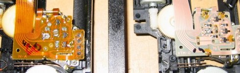
Here you can see the difference between the original CDM12.1 (left) and the first VAM. Look at the color of the PCB.
The next two VAM's has a similar color to the 12.1. They were specified to be a spare part for a Grundig CD.
I suspect the first one to be cheap East - it was specified to be a part for a Philips CD. It lasted for 3 days, then it became even mere noisy than the 12.1.
When I get the time, I'll try to gently oil the driveshaft, a drop of oil could cure the noise.
Benefits? The noise stopped and the new laser will do CD-R's.
Attachments
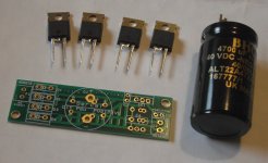
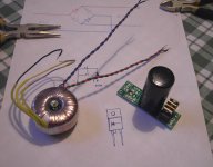
HEXFRED diodes, 2 x 9V @ 369mA toroid, 4700uF/40V BHC cap. And I've decided to put them on one of these lovely new Sercal boards, which saves me thinking too hard about wiring the diode bridge up. It's also smaller than my efforts with veroboard turned out.
There'll be two of these, one for each clock.
I know I could be accused of selling my buddy's company here, but these boards are a dream to solder to. This is one thing I can't lift pads from!
Simon
There'll be two of these, one for each clock.
I know I could be accused of selling my buddy's company here, but these boards are a dream to solder to. This is one thing I can't lift pads from!
Simon
Attachments
Glenn2 said:Simon, are you keeping Brent's business afloat single-handed?
Great to see you guys are still at it.

Good to "see you" too Glenn. I actually really just wanted these PCBs, they're handy and neat!
Simon
Glenn2 said:Simon, are you keeping Brent's business afloat single-handed?
Great to see you guys are still at it.
TBH Simon has had very little off me considering the amount of time we have made these different parts
once he is less skint he may also spend a few more squid 
Brent
rowemeister said:Bloody hell Simon I only got them in today, you waste no time
Brent
Normally I do... but I just wanted a break from soldering annoying things, to solder something easy and enjoyable. And why is it I'm starting to think my £10 Maplin soldering station isn't good enough? I need a Weller one with a nice silicone power cable and smaller handle, much easier to use. Also my solder-sucker wants a silicone tip. I'm realising the right tools make life so much easier, as in most DIY.
But you've got to own some cr@p ones before you can fully appreciate what's important. The things like how quickly an iron heats up, how a short and inflexible cable can get in the way, or how poorly a tip is held in place by the clamping mechanism all make the job annoying or enjoyable.
Simon
The product is not released fully yet as I was testing them today.
One nice feature of this pcb is that it is dual sided, +ve one side and -ve the other. You cannot of course use both at the same time but some trick track work has been done to get it to work.
I will get some info up this week
Brent
One nice feature of this pcb is that it is dual sided, +ve one side and -ve the other. You cannot of course use both at the same time but some trick track work has been done to get it to work.
I will get some info up this week
Brent
SimontY said:
Normally I do... but I just wanted a break from soldering annoying things, to solder something easy and enjoyable. And why is it I'm starting to think my £10 Maplin soldering station isn't good enough? I need a Weller one with a nice silicone power cable and smaller handle, much easier to use. Also my solder-sucker wants a silicone tip. I'm realising the right tools make life so much easier, as in most DIY.
But you've got to own some cr@p ones before you can fully appreciate what's important. The things like how quickly an iron heats up, how a short and inflexible cable can get in the way, or how poorly a tip is held in place by the clamping mechanism all make the job annoying or enjoyable.
Simon
Indeed

Brent
Brent is my C1 okay?
When reassembling my machine I must have pulled out the ground wire from my C1, have since reattached it and the player will not spin a disk. There is 0V across the + and GRND on the C1, however when the wires are disconnected from the clock board, they have a healthy 4.98.
When reassembling my machine I must have pulled out the ground wire from my C1, have since reattached it and the player will not spin a disk. There is 0V across the + and GRND on the C1, however when the wires are disconnected from the clock board, they have a healthy 4.98.
Thanks
It had been running from a 7805 just fine for month, then the GND wire got yanked off and after putting it back it looked deadish.
Just to have one last test before sending it for examination/post-mortem; where can the ground wire be attached, I put it on the pad by the 0 and well below the pad marked +.
The pad marked 0 is fine. The reg will have put Vin voltage onto it's output with the ground missing as it lost its reference.
Does your clock have the MM74HCT7M chip @ the output (we have 2 versions). If so this is the chip that will have blown as it's designed to run at no more than 5V. If you are confident of changing this smt chip you can do, if not pop it back to me to sort out for you.
Brent
Does your clock have the MM74HCT7M chip @ the output (we have 2 versions). If so this is the chip that will have blown as it's designed to run at no more than 5V. If you are confident of changing this smt chip you can do, if not pop it back to me to sort out for you.
Brent
- Home
- Source & Line
- Digital Source
- Marantz CD63 & CD67 mods list