Re: Re: Re: Re: A minor update
I'll try.
If you take a good look at the DAC datasheet and the PCB layout, I'll guess you can figure it out. The important part to notice is, that the DAC's AGND is[/] connected to a starground at the RCA - that's AGND. The problem is that this connects to the topplane of the PBC (like all other GND in the machine).
Remember the ground to the separate PSU supplying the DAC AVDD1-4 (U200), the AVSS1 and AVSS2, that's also analog side of the DAC.
I'm not using the starground on the PCB, I pick up the AVSS1 and 2 at U197 and U198. Remove these and connect the DAC side of both to your new AGND point (mine is between my new RCA plugs.
My AGND has 4 wires.
1. U197
2. U198
3. GND to the Flea that feeds AVDD1-4 (U200)
4. GND to my supply to my discrete board.
All connected at RCA's.
That's it. Does it make sense? Sure it makes music")
Thomo said:
Hmm. Well, I'm just building all my cd67 mods into a cd63. The perfect time to be experimenting I think. Could you post a few more details about what you have done? or is it all on here already?
Cheers, Lee.
I'll try.
If you take a good look at the DAC datasheet and the PCB layout, I'll guess you can figure it out. The important part to notice is, that the DAC's AGND is[/] connected to a starground at the RCA - that's AGND. The problem is that this connects to the topplane of the PBC (like all other GND in the machine).
Remember the ground to the separate PSU supplying the DAC AVDD1-4 (U200), the AVSS1 and AVSS2, that's also analog side of the DAC.
I'm not using the starground on the PCB, I pick up the AVSS1 and 2 at U197 and U198. Remove these and connect the DAC side of both to your new AGND point (mine is between my new RCA plugs.
My AGND has 4 wires.
1. U197
2. U198
3. GND to the Flea that feeds AVDD1-4 (U200)
4. GND to my supply to my discrete board.
All connected at RCA's.
That's it. Does it make sense? Sure it makes music
Re: Re: Re: Re: Re: A minor update
It makes sense to me.... and it seems easy to implement also.
Of course you will need a separate psu for this modd.....
One question remains... your RCA plugs also connect to the general GND of the player ?
Ricardo
avr300 said:
I'll try.
If you take a good look at the DAC datasheet and the PCB layout, I'll guess you can figure it out. The important part to notice is, that the DAC's AGND is[/] connected to a starground at the RCA - that's AGND. The problem is that this connects to the topplane of the PBC (like all other GND in the machine).
Remember the ground to the separate PSU supplying the DAC AVDD1-4 (U200), the AVSS1 and AVSS2, that's also analog side of the DAC.
I'm not using the starground on the PCB, I pick up the AVSS1 and 2 at U197 and U198. Remove these and connect the DAC side of both to your new AGND point (mine is between my new RCA plugs.
My AGND has 4 wires.
1. U197
2. U198
3. GND to the Flea that feeds AVDD1-4 (U200)
4. GND to my supply to my discrete board.
All connected at RCA's.
That's it. Does it make sense? Sure it makes music
It makes sense to me.... and it seems easy to implement also.
Of course you will need a separate psu for this modd.....
One question remains... your RCA plugs also connect to the general GND of the player ?
Ricardo
Re: Re: Re: Re: Re: Re: A minor update
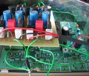
GND of the discrete goes to GND of it's PSU - and on to the AGND. As a matter of fact I let the U197 & U198 enter the discrete board at it's input end and connects the grounds (left and right) at output end of the discrete to the RCA's.
This picture illustrates it. 3 wires in at input end, LO, LON and U198 (RO, RON and U197) and 2 GND wires at output end + Flea GND + analog PSU GND.
Don't get confused over the LR outputs from the discrete.
RCruz said:
It makes sense to me.... and it seems easy to implement also.
Of course you will need a separate psu for this modd.....
One question remains... do you or do you not connect the GND of your discrete board to the GND in the player ?
Ricardo
GND of the discrete goes to GND of it's PSU - and on to the AGND. As a matter of fact I let the U197 & U198 enter the discrete board at it's input end and connects the grounds (left and right) at output end of the discrete to the RCA's.
This picture illustrates it. 3 wires in at input end, LO, LON and U198 (RO, RON and U197) and 2 GND wires at output end + Flea GND + analog PSU GND.
Don't get confused over the LR outputs from the discrete.
Attachments
Re: Re: Re: Re: Re: Re: Re: A minor update
Are your RCA´s isolated from the player (no gnd contact)?
Do you connect your analog psu GND to mains earth ?
Splendid work.
Ricardo
avr300 said:
GND of the discrete goes to GND of it's PSU - and on to the AGND. As a matter of fact I let the U197 & U198 enter the discrete board at it's input end and connects the grounds (left and right) at output end of the discrete to the RCA's.
This picture illustrates it. 3 wires in at input end, LO, LON and U198 (RO, RON and U197) and 2 GND wires at output end + Flea GND + analog PSU GND.
Don't get confused over the LR outputs from the discrete.
Are your RCA´s isolated from the player (no gnd contact)?
Do you connect your analog psu GND to mains earth ?
Splendid work.
Ricardo
Re: Re: Re: Re: Re: Re: Re: Re: A minor update
1. Yes, isolated.
2. Main earth - do you mean protective ground? You could, but why ? You don't need to.
(I have connected mine to my own separate earth rod exclusive for my audio) - but pls. be careful - understand the potential of 230V, groundloops and shock hazard.
RCruz said:
Are your RCA´s isolated from the player (no gnd contact)?
Do you connect your analog psu GND to mains earth ?
Splendid work.
Ricardo
1. Yes, isolated.
2. Main earth - do you mean protective ground? You could, but why ? You don't need to.
(I have connected mine to my own separate earth rod exclusive for my audio) - but pls. be careful - understand the potential of 230V, groundloops and shock hazard.
Re: Re: Re: Re: Re: Re: Re: Re: Re: A minor update
So in reality you have two separate PSU in the player...
1 - Psu Digital + GND on the main PCB
2 - Psu Analog for the dac and output discrete + One common AGND.....
And you do not connect both GND ever.
I never tried it because I believed some kind of (gnd leverage) was needed to make things work.
This is a major modd.
The sound must be so much better...
Very impressed.
avr300 said:
1. Yes, isolated.
2. Main earth - do you mean protective ground? You could, but why ? You don't need to.
(I have connected mine to my own separate earth rod exclusive for my audio) - but pls. be careful - understand the potential of 230V, groundloops and shock hazard.
So in reality you have two separate PSU in the player...
1 - Psu Digital + GND on the main PCB
2 - Psu Analog for the dac and output discrete + One common AGND.....
And you do not connect both GND ever.
I never tried it because I believed some kind of (gnd leverage) was needed to make things work.
This is a major modd.
The sound must be so much better...
Very impressed.
Re: Re: Caps on Super Rayregs
Hi Ricardo
Did you compare the regs with the tant and the Cerafine on the gyrator?
I have built my 5v regs with 4.7u tant/ BC547 VBE and 10u tant on the output, although I have built one with 100u/25v Cerafine on the output. I have used two 3.9v Zeners in parallel to set the voltage and get 5.3v, which I think is near enough.
I haven't had chance to fit them yet, so I cannot say what the difference is.
I'm not sure the bigger cap on the output will make a difference as I have 470u BG's as reservoir caps on the main pcb near to the chips replacing the original caps.
Peufeu said tants are not good at high frequencies nor are they good on distortion.
Although the Cerafines may be better caps, as we are talking power supply as opposed to signal purity, I am not sure what is best.
I thought smaller caps were faster, so that might be better for faster transient response.
Much as I would love to use Brent's sPower regs, I cannot afford them, so my solutions must be home made.
I know Simon and Thomo are mightily impressed with them for speed, etc, but I'm not sure what makes a reg "fast".
Regards
Jim
PS good luck with separating the grounds.
RCruz said:
State of the Art....
Relating to sregs, I am using 317 based ones, built using red leds instead of resistors to set the voltage. Also using a capacitance multiplier. On the outputs I have Cerafine and BG depending on the reg use.
Here you have the components:
R122 (+5v PSU DIGITAL) +5V Sreg (LM317 + 2xRed Led bypassed by 220uF Elna + 121r (pins 1-2) + gyrator (BC550C + 120uF Pana FC) + 100uF25v ELNA Cerafine output
R123 (+5v PSU ANALOG) +5V Sreg (LM317 + 2xRed Led bypassed by 10uF Tant + 121r (pins 1-2) + gyrator (BC550C + 120uF Pana FC) + 220uF BG STD output
With these regs on the servo I get Deep tight bass, big overall detail improvement.
Ricardo
Hi Ricardo
Did you compare the regs with the tant and the Cerafine on the gyrator?
I have built my 5v regs with 4.7u tant/ BC547 VBE and 10u tant on the output, although I have built one with 100u/25v Cerafine on the output. I have used two 3.9v Zeners in parallel to set the voltage and get 5.3v, which I think is near enough.
I haven't had chance to fit them yet, so I cannot say what the difference is.
I'm not sure the bigger cap on the output will make a difference as I have 470u BG's as reservoir caps on the main pcb near to the chips replacing the original caps.
Peufeu said tants are not good at high frequencies nor are they good on distortion.
Although the Cerafines may be better caps, as we are talking power supply as opposed to signal purity, I am not sure what is best.
I thought smaller caps were faster, so that might be better for faster transient response.
Much as I would love to use Brent's sPower regs, I cannot afford them, so my solutions must be home made.
I know Simon and Thomo are mightily impressed with them for speed, etc, but I'm not sure what makes a reg "fast".
Regards
Jim
PS good luck with separating the grounds.
Re: Re: Re: Caps on Super Rayregs
If you mount the regs right next to the BG on the main board, you shouldn't need the output cap on the reg itself.
I use all my regs like this and have found it a small improvement.
Someone correct me if I'm wrong though.
Lee.
jimh0612 said:
I'm not sure the bigger cap on the output will make a difference as I have 470u BG's as reservoir caps on the main pcb near to the chips replacing the original caps.
If you mount the regs right next to the BG on the main board, you shouldn't need the output cap on the reg itself.
I use all my regs like this and have found it a small improvement.
Someone correct me if I'm wrong though.
Lee.
Re: Re: Re: Caps on Super Rayregs
Hi Jim
If you want to use output caps, you can always bypass big caps with smaller ones (ex: 3u3 tant + 4700pF styroflex+2200uF Rubycon) to increase speed and transiente response, but, as you have the BG´s on the PCB near the chip, I believe you do not need output caps on the sregs.
Also the BG should not be bypassed.
Brent´s SPower are much better regs because they are very fast... So the output voltage does not get affected with variations on the load.
You will love the results if you power the servo with two sregs... You will gain a lot of detail.
Regards
Ricardo
jimh0612 said:
Hi Ricardo
Did you compare the regs with the tant and the Cerafine on the gyrator?
I have built my 5v regs with 4.7u tant/ BC547 VBE and 10u tant on the output, although I have built one with 100u/25v Cerafine on the output. I have used two 3.9v Zeners in parallel to set the voltage and get 5.3v, which I think is near enough.
I haven't had chance to fit them yet, so I cannot say what the difference is.
I'm not sure the bigger cap on the output will make a difference as I have 470u BG's as reservoir caps on the main pcb near to the chips replacing the original caps.
Peufeu said tants are not good at high frequencies nor are they good on distortion.
Although the Cerafines may be better caps, as we are talking power supply as opposed to signal purity, I am not sure what is best.
I thought smaller caps were faster, so that might be better for faster transient response.
Much as I would love to use Brent's sPower regs, I cannot afford them, so my solutions must be home made.
I know Simon and Thomo are mightily impressed with them for speed, etc, but I'm not sure what makes a reg "fast".
Regards
Jim
PS good luck with separating the grounds.
Hi Jim
If you want to use output caps, you can always bypass big caps with smaller ones (ex: 3u3 tant + 4700pF styroflex+2200uF Rubycon) to increase speed and transiente response, but, as you have the BG´s on the PCB near the chip, I believe you do not need output caps on the sregs.
Also the BG should not be bypassed.
Brent´s SPower are much better regs because they are very fast... So the output voltage does not get affected with variations on the load.
You will love the results if you power the servo with two sregs... You will gain a lot of detail.
Regards
Ricardo
Wahhhh (Not Wham, Last Xmas I Gave You My Heart... or stop modding your CDP)
Folk still improvin' CDPs here!
Nice to see I'll get your knowledge next time I'll have a look in.
Right now will just fit new gold plated RCAs (I've stock but think it's more for show than anything else...) and my Vibrapod feet (shaking rack...).
Like I often do I'll be happy if people here can have a look there:
http://www.diyaudio.com/forums/showthread.php?s=&postid=1502572#post1502572
Thanks,
Matthieu
Don't get me started on caps, lol.
As you can see the ESR of those is ludicrous. Tant drops are useless.
Solid tantalum chip caps, those have better ESR. Actually the ESR is a desirable characteristic in this case to stabilize the LDO in portable equipment and avoid ringing with the ceramic caps. 0.2-0.5 ohms is cool, 5 ohms like above is a joke.
Of course OSCON is always a safe choice, this cap is so fast, still less than 0.1 ohm at 10 MHz, of course at those frequencies trace inductance matters (better use it close to the chip's pin and bypass to ground plane).
Here is a standard stacked poly film through hole cap, it's pretty obvious that the OSCON is a lot better for bypassing : OSCON has something like 50 times less inductance, and a tiny bit more ESR to damp those nasty ringings.
Obviously for a signal coupling cap or filter cap, this would be different. But, note for HF filtering applications (like lowpass at the output of a DAC for instance), capacitor inductance should not be neglected.
However not all films are equal and using this in a filter would introduce "interesting" parasitic effects since at the frequency of interest, the capacitance starts to go to fairy land.
And finally a good old snap-in of low inductance construction ; those are pretty cheap too ; the 1000µF would be pretty useless but the 6800 and 22000 are really looking good, still not inductive at 100 kHz, flat low impedance, a small bypass (perhaps OSCON) and you get less than 0.1 ohm power supply impedance up to 10 MHz which is pretty impressive.
A standard through-hole lytic will display much worse performance.
However, the regulator will take care of the power supply impedance (hopefully) up to a certain frequency, depending on its speed, so a faster regulator can allow the use of a smaller value cap, in this case Panasonic FK or FA series can be applied, those are low-ESR, low-ESL caps for switchmode supplies, pretty cheap too.
Note that at 10 MHz, 0.1 ohms impedance is just a few nanohenries away so trace length matters, and ground plane is mandatory...
What I also wanted to mention is that, if you misguidedly bypass the above snap-in cap (30 nH, 10mOhm) with the above 10 uF stacked film (40nH, 8mOhm), with 10 mm of PCB trace (5 nH), you get a RLC with about 10uF, 75nH, 18 mOhm, so resonance is at 1.1 MHz with a Q of 4, which means it will ring. This is a problem with multiple bypasses. In the classical case of a PCB without a ground/power plane, power is distributed through rather long traces, with multiple bypass caps, which worsens the effect.
Extra reading :
http://www.analog.com/library/analogdialogue/archives/39-09/layout.html
An externally hosted image should be here but it was not working when we last tested it.
As you can see the ESR of those is ludicrous. Tant drops are useless.
An externally hosted image should be here but it was not working when we last tested it.
Solid tantalum chip caps, those have better ESR. Actually the ESR is a desirable characteristic in this case to stabilize the LDO in portable equipment and avoid ringing with the ceramic caps. 0.2-0.5 ohms is cool, 5 ohms like above is a joke.
An externally hosted image should be here but it was not working when we last tested it.
Of course OSCON is always a safe choice, this cap is so fast, still less than 0.1 ohm at 10 MHz, of course at those frequencies trace inductance matters (better use it close to the chip's pin and bypass to ground plane).
An externally hosted image should be here but it was not working when we last tested it.
Here is a standard stacked poly film through hole cap, it's pretty obvious that the OSCON is a lot better for bypassing : OSCON has something like 50 times less inductance, and a tiny bit more ESR to damp those nasty ringings.
Obviously for a signal coupling cap or filter cap, this would be different. But, note for HF filtering applications (like lowpass at the output of a DAC for instance), capacitor inductance should not be neglected.
An externally hosted image should be here but it was not working when we last tested it.
However not all films are equal and using this in a filter would introduce "interesting" parasitic effects since at the frequency of interest, the capacitance starts to go to fairy land.
An externally hosted image should be here but it was not working when we last tested it.
And finally a good old snap-in of low inductance construction ; those are pretty cheap too ; the 1000µF would be pretty useless but the 6800 and 22000 are really looking good, still not inductive at 100 kHz, flat low impedance, a small bypass (perhaps OSCON) and you get less than 0.1 ohm power supply impedance up to 10 MHz which is pretty impressive.
A standard through-hole lytic will display much worse performance.
However, the regulator will take care of the power supply impedance (hopefully) up to a certain frequency, depending on its speed, so a faster regulator can allow the use of a smaller value cap, in this case Panasonic FK or FA series can be applied, those are low-ESR, low-ESL caps for switchmode supplies, pretty cheap too.
Note that at 10 MHz, 0.1 ohms impedance is just a few nanohenries away so trace length matters, and ground plane is mandatory...
What I also wanted to mention is that, if you misguidedly bypass the above snap-in cap (30 nH, 10mOhm) with the above 10 uF stacked film (40nH, 8mOhm), with 10 mm of PCB trace (5 nH), you get a RLC with about 10uF, 75nH, 18 mOhm, so resonance is at 1.1 MHz with a Q of 4, which means it will ring. This is a problem with multiple bypasses. In the classical case of a PCB without a ground/power plane, power is distributed through rather long traces, with multiple bypass caps, which worsens the effect.
Extra reading :
http://www.analog.com/library/analogdialogue/archives/39-09/layout.html
Re: Really joyfull
Hi Ricardo
Sorry for the late reply but i've moved house this weekend and have no broadband until it all exchanges over.
I'm glad you like the reg
Brent
RCruz said:
Hi Brent
Just replaced my old home made sreg by the Spower with 1x 470uF BG on the output.
The Spower is now replacing U199 in a dedicated small pcb.
Power comes from U161 "output of C813" and ground to Floating Star Earth.
This modd gives improvements in overall fluidity of the sound. I noticed enormous improvements in the bass integration and inteligibility , less harshness/stridency in the high frequencies.
Regards
Ricardo
Hi Ricardo
Sorry for the late reply but i've moved house this weekend and have no broadband until it all exchanges over.
I'm glad you like the reg
Brent
http://www.diyaudio.com/forums/showthread.php?postid=1502650#post1502650
You mean that multiple bypassing a large cap might cause ringing ?
Can you please provide a little more detail and if possible a practical example ?
I am now building a psu for the dac analog sreg so I am particularly interested in your comments about snap in versus t hole big electrolitics... What is the reasoning behind the differences? (Reading about big caps I always found that for the same values, screw terminal ones present better ESR than T-hole ones... but why?)
Best regards
Ricardo
> You mean that multiple bypassing a large cap might cause ringing ?
Yep.
> Can you please provide a little more detail and if possible a practical example ?
Well, caps have inductance, traces have inductance, as soon as there is more than one cap it makes a LC circuit...
Just like transformer inductance + parasitic capacitance of rectifier diodes = big burst of RF 100 times a second (that's why we put snubbers and fancy diodes)
Now you can calculate the resonant frequency and the Q to have proper damping, but it's pretty difficult to do since most of the time the interesting bits aren't specified in the datasheet... ideally this would need to be done with a network analyzer (I'm working on this, lol). So, sorry I can't really be of any help, except provide generic advice like : don't bypass a large electrolytic with very low ESR with a large film cap with high inductance (and also very low ESR), also avoid inductive caps (wound caps, anything with the leads on both ends like "audiophile" caps etc which are meant for signal coupling)... Read the page on RLC circuits on Wikipedia
> snap in versus t hole big electrolitics
Essentialy, a snap-in cap is a big thru-hole electrolytic cap, except it's easier to solder (it snaps in so it doesn't fall when you flip the board) and optimized for low ESR and low impedance... good for high-current switchmode power supplies for instance. Audiophile caps like Cerafine etc are also low-impedance I believe, but generic no-name through-hole caps are really bad...
Take Panasonic for example, they make lots of different caps, the performance of the "general purpose" is very different from the "FA/FK low impedance" series, try to smooth the noise from a switchmode power supply with a "general purpose" cap, it just won't work, too much inductance and ESR... now put a more optimized cap and no more problems, of course they are much more expensive (that means $1/cap instead of $0.2 lol)
> I always found that for the same values, screw terminal ones present better ESR than T-hole ones... but why?
Because those are made for extra-super-heavy duty power supplies and therefore they must handle lots of current... Power dissipation in the cap is RI² you probably know that, so if R is too much, the cap will overheat, so those caps are optimized to handle that situation, that's all. But those are not necessarily low-impedance at higher frequencies, also you have to add the inductance of wires etc. Switching power supplies are another thing, since the cap sees lots of current at high frequency, so it must have low ESR and low inductance, which means it is on the PCB with small leads or SMD.
I just built a LED driver for my bike, it's a switcher with LTC3780, the smoothing cap is a 220uF SMD cap, pretty small (about 8x8 mm), it eats up to 2 amps of ripple current, a crummy lytic with 1 ohm ESR would just explode. I get 20 mV ripple.
Do you need to bypass the big PSU caps before the regulator ? That depends... if your regulator is slower than say, the 100-500 kHz bandwidth of a nice snap-in cap, which is most likely the case, bypassing the big cap isn't necessary (put snubbers on your rectifier however, another can of worms to design those). And, if your big caps are like 5 cm away from your regulator, wire inductance makes your bypass cap useless anyway.
For the digital sections, or the analog sections of the DAC :
big PSU caps -> regulator -> cap -> choke -> OSCON // 100 nF X7R at the chip
(if you have more digital chips to feed, add more chokes and caps, for instance Murata BLMA 1206 SMD ferrites are nice). The cap after the regulator extends its bandwidth, and the choke prevents ringing and keeps the digital noise confined. Don't overdo it with the choke, try BLM31A700S for instance. A choke will keep RF out of your wires which is a good thing.
For the opamps :
This is where it gets hairy. Fast opamps need local bypass and multiple bypass caps with long traces do ring. Solution could be to use chokes again, or simply use a post-regulator cap with a reasonable amount of ESR (like 0.1-0.3 ohms) which will damp the ringing.
I need to finish this network analyzer, because here I'm shooting in the dark.
- Home
- Source & Line
- Digital Source
- Marantz CD63 & CD67 mods list