martin clark said:Simon you're player's broken again
")
O rly
Actually I was just thinking that as well as the music coming through so clearly with this player now, also the weakness of her vocals is extremely evident like never before! So nope - not broken, I just have poor taste

Re: Kwak clock
Hi Jim,
The FET oscillator outputs a sine wave and the AD8561 comparator transforms this into a square wave. This is a better waveform to use as a clock signal because it has steep edges. The duty-cycle is the ratio between the on-time and total period time of the square wave. If the on and off times are equal, the duty-cycle is 50%. With the trimmer you can set the level at which the comparator switches, and when you set the duty-cycle to 50% you know it switches exactly at the center of the sinewave.
A soundcard is not very suited to measure the clock signal. It will only measure audio signals upto 20kHz if you're lucky, and the clock is at 16934400kHz, so that won't work. The best way to set P1 if you don't have a scope is with a multimeter. Set it to measure mV DC volts and connect it to pins 2 and 3 of the comparator. Now adjust P1 for a 0mV reading. That will get you pretty close.
If you're going to connect the clock to the SM5872 DAC (pin 28) in your player, you could also do without the comparator. Inside the DAC there's a similar circuit that will convert the sine into a square wave. You can take the clock signal directly from R5, with a 10 or 22n capacitor in series.
Regards,
Ray
jimh0612 said:Hi Ray
...
Two questions please.
1) Can you explain what you mean by 50% duty cycle and
2) Although I do not have an oscilloscope I have read of using software and a PC soundcard.
I have a PC with a Soundblaster Live! card in it.
How would I use this to make the adjustment please?
Thanks
Jim
Hi Jim,
The FET oscillator outputs a sine wave and the AD8561 comparator transforms this into a square wave. This is a better waveform to use as a clock signal because it has steep edges. The duty-cycle is the ratio between the on-time and total period time of the square wave. If the on and off times are equal, the duty-cycle is 50%. With the trimmer you can set the level at which the comparator switches, and when you set the duty-cycle to 50% you know it switches exactly at the center of the sinewave.
A soundcard is not very suited to measure the clock signal. It will only measure audio signals upto 20kHz if you're lucky, and the clock is at 16934400kHz, so that won't work. The best way to set P1 if you don't have a scope is with a multimeter. Set it to measure mV DC volts and connect it to pins 2 and 3 of the comparator. Now adjust P1 for a 0mV reading. That will get you pretty close.
If you're going to connect the clock to the SM5872 DAC (pin 28) in your player, you could also do without the comparator. Inside the DAC there's a similar circuit that will convert the sine into a square wave. You can take the clock signal directly from R5, with a 10 or 22n capacitor in series.
Regards,
Ray
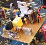
Attachments
selo said:thanks much.
here i can get hold of easily the SuperTjoebClock which is 300 euros with transformer. if this is not ok, then i can get something you recommend from the uk.
Hi Selo,
Personally I think 300 euros is a lot of money for a clock, but that's from a guy who builds his own.
. You could take a look around on E-Bay for Audiocom or similar products. The Kwak-based version mentioned in the above two messages is a simple but effective beginners project if you want to build it yourself.If you have no idea about electronics, maybe it's a good idea to find someone that does, so you can get a bit of help. Do you have some experience with a soldering iron? Otherwise it's going to be difficult to upgrade the player on a component level.
Regards,
Ray
jimh0612 said:Ray
Thanks for that.
As I already have all the parts I could either go ahead and include it, or perhaps use the comparator in a voltage regulator perhaps?
Would leaving the comparator out of the clock circuit make any appreciable difference?
Rgds
Jim
Hi Jim,
If you already have it, i'd recommend to include it. That way the DAC is fed with a nice square wave, which is better. The 10/22n cap is more some kind of budget version, as the comparator can be quite expensive.
Regards,
Ray
6h5c said:
If you use the digital out, you bypass the internal D/A converter and the analog output and filter. But there are plenty of areas that apply for modifications. A dedicated clock will help absolutely. The digital signal is produced by the decoder, which also runs on the clock signal. The power supply section around the decoder can be upgraded, and the section that supplies the transport, servo and drivers.
Here's a mods list with some highlighted areas, that should give you a rough idea of all the things that can be upgraded. Also the coupling cap CT01 and the digital-out transformer can be upgraded.
Regards,
Ray
Hi Ray
Can you please give an alternative to CT01 and output transformer ?
And what about the C514 (47p) .... what is it for ?
Thank you for your valuable comments
Ricardo
jimh0612 said:Approx. £3.50 at Farnell.
Jim
Indeed, very expensive compared to the other components. Besides, i'm dutch
.RCruz said:Hi Ray
Can you please give an alternative to CT01 and output transformer ?
And what about the C514 (47p) .... what is it for ?
Thank you for your valuable comments
Ricardo
Hi Ricardo,
For CT01 you can take a 100n film cap, MKT or MKP. CT02/03/04 all couple the digital ground to the player's ground for AC signals. They can also be upgraded, although some have reported good results with bypassing them, or removing them. It all depends a bit on the input circuitry of the DAC. If your DAC already has a transformer at the input, you might consider bypassing the one in the player. Experiment is the keyword here
.C514 acts as a filter, together with R514. You could upgrade it to a polystyrene if you like.
Ray
6h5c said:
C514 acts as a filter, together with R514. You could upgrade it to a polystyrene if you like.
Thank You Ray
I will report my mods.
Regards
6h5c said:Indeed, very expensive compared to the other components. Besides, i'm dutch
Ahhh, is that like being Scottish or from Yorkshire?

SimontY said:Ahhh, is that like being Scottish or from Yorkshire?
 never met any Scots, but they always say us dutchies are cheap :bs:
6h5c said:
OMG - if a Scot tells you that you are cheap that is baaaaad.
My grandad was a mixture of Scottish and Jewish. If you believe in stereotypes, that would make him the tightest tightwad on the planet.... and he was!
Glenn2 said:OMG - if a Scot tells you that you are cheap that is baaaaad.
Nah, they only try to hide their own
!jimh0612 said:
...........Would leaving the comparator out of the clock circuit make any appreciable difference?................
There are several clock circuits around which do no use a comparator. Remember that (at least in the CD63) the clock replaces the crystal which feeds into fast gates in the dac chip.
Definately an sonic improvement and you can 'upgrade' to the comparator later.
Andy
Although I have some Yorkshire blood (and am married to a Yorkshirewoman!!) it's not enough to stop me using the comparator.
However it is enough to make me build it myself instead of buying (sorry Brent!).
Just one more question please Ray.
The link from your site to download the eps format of the clock pcb doesn't seem to work for me.
Don't think it's anything I'm doing as I got the CD outputstage eps fine - opened in Photoshop with no problems at all.
I've nearly finished building it on tripad stripboard from Maplins but it's been a headache working out the connections for a novice, with trying to construct a groundplane out of the spare strips, and I thought I might try having a go at etching a pcb.
By the time I've bought a starter kit for about £12 from Maplins I could probably have bought a pcb but don't know where to find them on the net.
Jim
- Home
- Source & Line
- Digital Source
- Marantz CD63 & CD67 mods list